background image

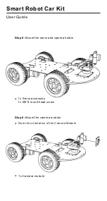
Step 5:

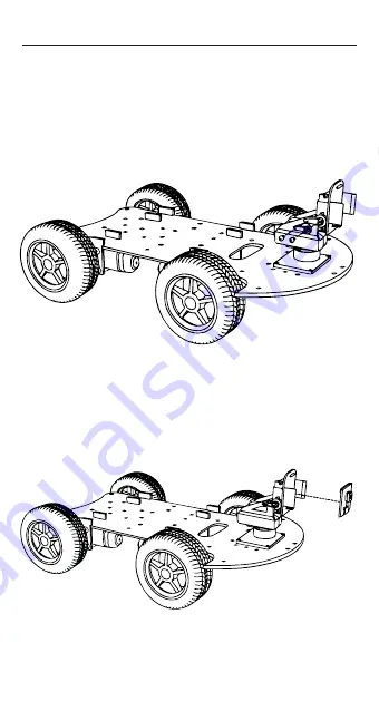
 Mount the servo and camera holder 

1 x Servo accessory
1 x M2*4 round head screw

*

Step 6:

 Mount the camera module

1 x Camera module

*

Note the orientation of the Camera Module

*

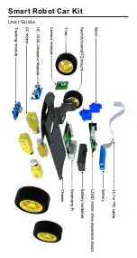
Smart Robot Car Kit 

User Guide

Summary of Contents for K0073

Page 1: ...Smart Robot Car Kit Quick Start Guide Model K0073...

Page 2: ...Smart Robot Car Kit User Guide...

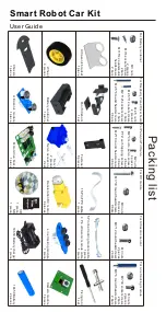
Page 3: ...Motor drive board 1 piece M3 5 4 countersunk headscrews 2 bars Packing list M3 30 screws round head 8 bars M2 5 6 screws round head 4 bars Chassis 1 piece Ultrasonic module 1 piece Deceleration DC mot...

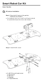
Page 4: ...tion marked on the chassis Step 2 Install the DC motor 8 x M3 30 round head screws 4 x DC motors 8 x M3 nuts 1 x Chassis 8 x T type fasteners For example the Front L and Front R marks should be matche...

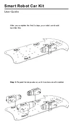
Page 5: ...After you complete the first 2 steps your robot car should look like this Smart Robot Car Kit User Guide Step 3 Repeat the steps above until 4 motors are all installed...

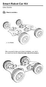
Page 6: ...2 Wheels installation 4 x Wheels Smart Robot Car Kit User Guide After a successful motors and wheels installation your robot car should look like this from the down side of the chassis...

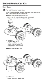
Page 7: ...d head screw 2 x PTZ self tapping screws Step 2 Mount the Pan servo 4 x M2 nuts 4 x M2 10 round head screws Smart Robot Car Kit User Guide Flip the chassis over from the last step and find the center...

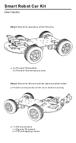
Page 8: ...t brackets 2 x Pan and Tilt accessory screws Step 4 Mount the tilt servo and the camera module holder 1 x Servo accessory 1 x Pan and Tilt bracket 2 x PTZ self tapping screws Find the center position...

Page 9: ...5 Mount the servo and camera holder 1 x Servo accessory 1 x M2 4 round head screw Step 6 Mount the camera module 1 x Camera module Note the orientation of the Camera Module Smart Robot Car Kit User G...

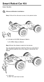
Page 10: ...Ultrasonic Module 1 x HC SR04 Ultrasonic Module Step 2 Mount the ultrasonic module to the chassis 2 x M3 nuts 2 x M3 12 round head screws Smart Robot Car Kit User Guide You can adjust the direction o...

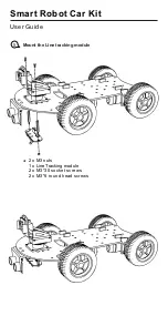
Page 11: ...5 Mount the Line tracking module 2 x M3 nuts 1 x Line Tracking module 2 x M3 30 socket screws 2 x M3 6 round head screws Smart Robot Car Kit User Guide...

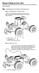
Page 12: ...Raspberry Pi Motherboard Note Pi is not included bring your own Pi for this step You might need to flip the chassis over to better install the nuts Note The ribbon has already been installed on the ca...

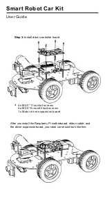
Page 13: ...M2 5 11 socket screws 4 x M2 5 6 round head screws 1 x Motor drive expansion board Smart Robot Car Kit User Guide After you install the Raspberry Pi motherboard ribbon cable and the driver expansion...

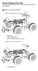
Page 14: ...tallation 2 x M3 nuts 1 x Battery container 2 x M3 6 socket screws 2 x M3 5 4 countersunk head screws Step 1 Install the Battery container Step 2 Insert two 18650 batteries Smart Robot Car Kit User Gu...

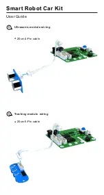
Page 15: ...Tracking module wiring 9 20cm 5 Pin cable Ultrasonic module wiring 8 20cm 4 Pin cable Smart Robot Car Kit User Guide...

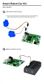
Page 16: ...and Tilt servos wiring 10 Connect the cables in the orientation shown in the illustration below Note the positions of the yellow and brown wires Battery container wiring 11 Smart Robot Car Kit User Gu...

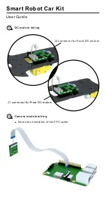
Page 17: ...DC motors wiring 12 J2 connector for Front DC motors J1 connector for Rear DC motors Camera module wiring 13 Note the orientation of the FPC cable Smart Robot Car Kit User Guide...

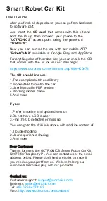
Page 18: ...roducts Contact us Customer support support uctronics com Business sales uctronics com Tel 86 025 84271192 Web http www uctronics com contacts Smart Robot Car Kit User Guide After you finish all steps...

Reviews: