background image

Important

Notice

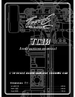
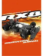
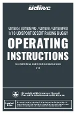
FULL PROPORTIONAL REMOTE CONTROL UDIRACING SERIES

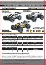
1/18 UDISPORT DESERT RACING BUGGY

UD1805 / UD1805PRO / UD1806 / UD1806PRO

Our company's products are improving all the time,design and specifications are subject to 

change without notice. All the information in this manual has been carefully checked to ensure 

accuracy, if any printing errors, our company reserve the final interpretation right.

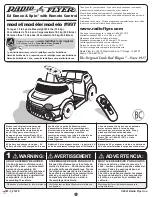
This product is suitable for users over 14 years old.

Please read this instruction manual carefully befores use.

OPERATING

INSTRUCTIONS

V1.0

Summary of Contents for UD1805

Page 1: ...g all the time design and specifications are subject to change without notice All the information in this manual has been carefully checked to ensure accuracy if any printing errors our company reserve the final interpretation right This product is suitable for users over 14 years old Please read this instruction manual carefully befores use OPERATING INSTRUCTIONS V1 0 ...

Page 2: ...tions carefully before proceeding The model must stop immediately and check for the reasons when it is operating abnormal Keep in mind that people around you may also operate a radio control model The motor is a heating part please do not touch it If you don t use the model for a long time please raise the chassis to let the wheels hang in the air Please keep the package or instructions as they co...

Page 3: ...wer supply and pull out the plug 2 Remove the battery from the model before charging 3 DO NOT charge the battery when it is bulging or expanding 4 Keep away from damp corrosive environment and heat source 5 Please charge the battery under adult supervision 6 Pay attention to the polarity of the battery when installing or replacing the battery 7 Different types of batteries or old and new batteries...

Page 4: ...ow charger it in time or replace it with new battery Please make sure the wheel or drive shaft is entangled by debris and remove it The motor may have reached the expiration date replace with the same motor Please keep the car within effective control distance When the battery of the transmitter in low battery please replace it in time Check whether all parts of the model car are damaged and repla...

Page 5: ...mmary Power switch 1601 004 1805 015 1805 014 1601 015 1805 011 1601 035 1805 012 1805 006 1601 016 1805 009 1805 010 1805 003 1806 003B 1805 004 1601 007 1805 006 1805 007 1805 007 1805 008 1601 011 1601 012 1601 013 ...

Page 6: ...06 Power switch 1805 001 1806 001 1805 002 1806 002 1806 003A 1805 006 1806 003A 1805 005 S1701 ESC01W ...

Page 7: ...07 1601 011 ESC01W Antenna Antenna Electronic speed controller Motor Motor Power switch Steering servo Steering servo Taillight Taillight Headlight Headlight Model Battery Model Battery ...

Page 8: ...ly When the power of the transmitter is low the indicator light will flash slowly The above situation should be handled as soon as possible to avoid accidents Steering reverse Steering range adjustment knob Low Min Max High Transmitter function main interface Default steering wheel direction Default throttle trigger direction Forward Backward Brake Turn left Turn right Throttle speed limit switch ...

Page 9: ...nction and sensitivity of the car gyroscope sensor can be adjusted through the ESP knob of the transmitter Adjustment of gyroscope action ratio Steering trim Steering range adjustment When the steering wheel is in the center position if the car can not drive in a straight line please use the steering trim knob to adjust and correct the left and right directions of the front wheels The steering ran...

Page 10: ...ng the charging indicator is flashing and the indicator is always on after charging Do not put the battery in the model when charging The battery must be cooled before charging The battery contains less power when leaving the factory so it must be charged and saturated before use Battery input port Model Battery Charger output port Charging Charger box Power USB adapter not included Please use the...

Page 11: ... battery compartment Battery hold down reset clips reset and then connect with the ESC Operational guidance Frequency matching Place the model on level ground Do not touch the throttle trigger when turning on thepower of the transmitter OFF ON 1 Turn on the power of the transmitter and the red indicator light will flash quickly Consistent direction ...

Page 12: ...yroscope is being calibrated automatically Please place the car on the level ground to complete this operation After calibration the car lights return to normal 2 Press for 2 second to turn on the power The lights flash and enter the frequency matching state Press for 2 second to turn off the power ESC01W Power on method ESC01W 2 Press for 2 second to turn on the power The lights flash and enter t...

Page 13: ...teering wheel Throttle trigger Steering wheel Throttle trigger Steering wheel Throttle trigger Low speed High speed Brake Backward Pull the throttle trigger back gently and the car will move forward slowly The throttle trigger is pulled to the maximum and thecar moves forward quickly When the car is moving forward the throttle trigger is pushed forward and the car stops moving After the throttle t...

Page 14: ...01 016 Installation of wheels Use the hexagon nut wrench to take out the nut fixing the tire 1601 004 and remove the old tires Put on new tires Hexagon nut wrench Parts exploded view Front and rear shock absorbers Wheel Wheel ...

Page 15: ...ar suspension arm 1601 063 1601 063 1601 050 1601 051 1601 017 1601 021 1601 019 1601 022 1601 026 1805 011 1805 011 1805 015 1805 009 1805 009 1805 010 1601 050 1601 050 1601 051 1601 017 1601 021 1601 022 1601 026 1805 015 1805 012 1805 012 1805 009 ...

Page 16: ...y of front bumper Assembly of rear bumper 1601 039 1601 034 1601 035 1805 006 1601 055 1601 055 1601 064 1601 056 1601 062 1601 056 1805 008 1601 039 1601 042 1601 035 1601 034 1601 055 1601 056 1805 006 1805 008 ...

Page 17: ...17 Assembly of steering servo Assembly of front rear differentials 1601 029A 1601 033 1601 024 1601 024 1601 030 1601 031 1601 031 1601 031 1601 032 Steering servo ...

Page 18: ...sis Rear sopiler 1601 066 1601 002 1805 014 1805 014 1805 006 1601 015 1601 060 1601 034 1601 034 1805 006 1805 006 1601 013 1601 024 1601 024 1601 060 1601 056 1601 056 1601 049 1601 054 1601 054 1601 054 1601 062 ...

Page 19: ...19 Assembly of chassis Main propeller shaft system 1601 041 1601 017 1601 036 1601 017 1601 038 1601 021 1601 054 1601 053 1601 056 1601 056 1601 062 1601 056 ...

Page 20: ...assembly Body assembly Body clips 4 Headlight group UD1805 Headlight group UD1806 Wheel 2 Wheel 2 Wheel 2 Motor assembly 390 Motor assembly Brushless Steering servo 390 Motor Steering servo Brushless Front Rear shock tower assembly Front Rear shock absorber Front Rear bumper assembly Electronic speed controller Brushless Electronic speed controller 390 Motor Model battery Battery hold down Upper c...

Page 21: ...ers 4 Front Rear wheel carriers assembly Adjustable steering linkage Suspension arms front Suspension arms rear Driveshaft assembly 2 Differential assembly Servo saver Steering bellcrank Rudder connecting rod Differential housing Chassis Motor gear Motor mounts 390 Motor 1601 037B Motor mounts Brushless Main spur gear Bulkhead tie bars Main driveshaft Taillight group Charger ø5 5 149mm ...

Page 22: ...ar sopiler assembly 390 Motor mounts 2 4mm Transmitter Cross screwdriver Hex wrench Ø2 13mm PM Screw pin set 8 Ø2 5 16 5mm PM Screw pin set 8 Ø2 5 11 8mm PM Shoulder screws 8 Ø2 5 5mm PM Screws 8 Ø2 5 8 5mm KM Screws 8 Ø2 5 11 5mm KM Screws 8 Ø2 3 8mm PB Screws 8 Ø2 10mm PB Screws 8 Ø2 3 14mm PB Screws 8 Ø2 5 15mm PB Screws 8 Ø2 3 8 Ø8mm PB Screws 8 Ø2 3 5 Ø7mm PB Screws 8 ...

Page 23: ...Shoulder screws 8 Ø2 8mm PB Screws 8 Ø3 8mm KM Screws 8 Ø2 6 8mm PB Screws 8 Ø2 3 6mm PB Screws 8 1601 004 1601 017 1601 021 1601 033 1601 019 1601 024 1601 022 1601 026 Hex flanged nylon insert lock nut 4 M3 Ø8 Ø4 3mm Ball bearing 4 Ø12 Ø8 3 5mm Ball bearing 4 Ø2 5 10mm Pivot balls 4 Ø2 5 12mm Pivot balls 4 Ø1 8 6 8mm Pin 4 Ø2 5 32mm Pin 4 Ø2 5 21mm Pin 4 1601 063 1601 064 1601 065 1601 066 ...

Page 24: ...ollowing measures Reorient or relocate the receiving a ntenna Increase the separation between the equipment and receiver Connect the equipment into an outlet on a circuit different from that to which thereceiver is connected WARNING Changes or modifications not expressly approved by the party responsible for compliance could void the user s authority to operate the equipment This device complies w...

Reviews: