UE Systems ULTRAPROBE 10000, Manual
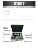
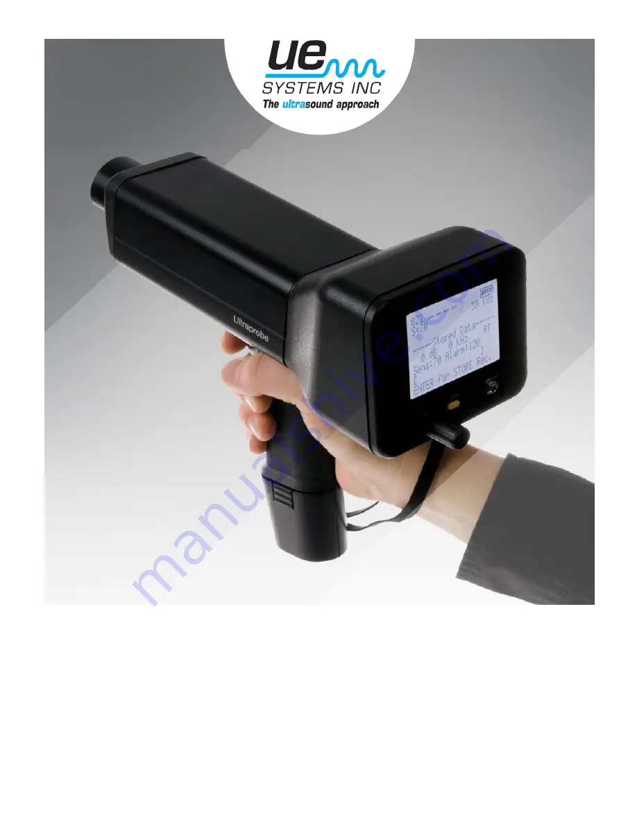
The UE Systems ULTRAPROBE 10000 is a cutting-edge inspection device for analyzing machinery and detecting faults. With its advanced features and user-friendly interface, this product enables maintenance professionals to easily identify issues and prevent downtime. Download the free user manual at 88.208.23.73:8080 and unleash the full potential of your ULTRAPROBE 10000.
Share
Download
Reviews:
No comments
Related manuals for ULTRAPROBE 10000

Mentor Visual iQ
Brand: GE Pages: 2

SV-1A
Brand: A&D Pages: 102

DOT
Brand: Xsens Pages: 4

Reference 3000
Brand: Gamry Pages: 16

PHOSPHAX indoor sc
Brand: Hach Pages: 104

Lange ORBISPHERE 3100
Brand: Hach Pages: 384

9065
Brand: Waltron Pages: 11

LaserRange-Master T2
Brand: LaserLiner Pages: 52

LaserRange-Master T4 Pro
Brand: LaserLiner Pages: 68

IPLEX TX
Brand: Olympus Pages: 4

IV0620C
Brand: Olympus Pages: 12

CX-3
Brand: Omano Pages: 14

MD50
Brand: Tavool Pages: 12

3020 M
Brand: Teledyne Analytical Instruments Pages: 107

AD-4408C
Brand: A&D Pages: 68

VideoPocket HD
Brand: LaserLiner Pages: 52

IPLEX RT
Brand: Olimpus Pages: 12

34058
Brand: KALEAS Pages: 64


