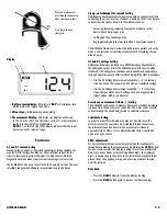
Low battery indicator
The
LOW BATTERY
i n d i cator displayed in the upper left hand corner of
the display screen alerts the operator to replace the ACM6000 battery.
• See “Battery Replacement” for detailed instructions
Temperature measurement
Automotive repair and maintenance often involves checking the
temperature of A/C and heating duct air as well as engine coolant
temperature. The operator may read temperature by connecting any
standard K type thermocouple to the input jacks, through the supplied
temperature probe adapter.
Hand strap
A Hand Strap is provided to avoid accidentally dropping the ACM6000
Clamp Meter.
Pouch
A pouch is provided for storage of the ACM6000 Clamp Meter, the
accessories and the operator’s manual.
Operating Instructions
AC/DC current testing
The procedure for measuring current using the ACM6000 is different
from measuring voltage.
• To measure VOLTAGE, the meter leads are connected to the points
in the circuit being tested
• To measure CURRENT, the jaws of the Clamp Meter are placed
around a wire or cable to make the measurement (Ensure test
leads are not connected to the meter)
1.
To measure high AC CURRENT:
Turn the rotary
function switch to the 200 Amps AC setting (200A ).
To measure high DC CURRENT:
Turn the rotary function switch
to the 200 Amps DC setting (200A ).
2. Slide the ACM6000 power switch to the ON position.
3. Press the
ZERO
button (DC current measurements, only).
This will zero the instrument for the most accurate reading.
4. Place the jaws of the ACM6000 around the conductor
being tested.
• Verify that the instrument and its strap do not
touch moving pulleys or belts
• Failure to obey the current flow polarity indicator
arrow located on the inner jaw face will result in a minus
sign to the left of the amps readout
• Be sure the jaws are closed, leaving no air gap between
the two jaws.
A. Remove the instrument from the conductor
B. Turn the rotary switch to the 20A scale
C. Follow steps 3 and 4
5. When testing is completed move the instrument power switch
to OFF.
Measuring AC voltage
NOTE:
Observe safety rules.
WARNING!
• Be certain that wires and leads, as well as clothing and hands
are clear of moving parts
• When checking ABS wheel speed sensors be sure the wheels
are free to rotate and will not move the vehicle or cause damage
1. Slide the ACM6000 power switch to the
ON
position.
2. Turn the rotary function switch to V.
3. Connect the test leads to the meter.
A. Plug the black lead into the COM input
B. Plug the red lead into the V
Ω
˚F input
4. Connect the probe tips to the circuit under test. For automotive
AC voltage measurements using a multimeter not necessary to
observe polarity.
NOTE:
If the voltage readout is not stable, further evaluation of the
c i rcuit using a labscope is re c o m m e n d e d .
5. When testing is completed move the instrument power switch
to
OFF
.
Measuring DC voltage
1. Slide the ACM6000 power switch to the
ON
position.
2. Turn the rotary function switch to V.
3. Connect the test leads to the meter.
A. Plug the black lead into the COM input
B. Plug the red lead into the V
Ω
˚F input
4. Connect the black COM probe tip to the ground (-) side of the
circuit under test.
5. Connect the red prove tip to the positive (+) side of the circuit.
• The voltage present in the circuit is shown on the display
panel readout
• Instrument will indicate the polarity of the red lead
connection displayed on the left side of the voltage readout
NOTE:
If the voltage reading is not stable, further
evaluation of the circuit using a labscope, model ADL7000
or ADL7100, is recommended.
6. When testing is completed move the instrument power switch
to
OFF
.
Resistance measurement
• The ACM6000 supplies a small current to the circuit under
test which is used to determine the circuit’s resistance
• Displays circuit resistance in Ohms (W)
ACM6000-MAN
P. 3

