4
ANALYZER OVERVIEW
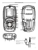
A. Infrared Printer Port
B. On/ Off (Power) Button
C. 6 Line Backlit Display
• Press any button to turn Back light on (will turn off after 10 seconds)
D. Protective Rubber Boot With Magnets
E. Status Bar Line
F. Data Hold Button:
Short press to hold current data.
G. Pump Toggle Button:
Long press to toggle pump on and off
H. UP Button
• Short press to navigate “UP”.
I. Save Log Button:
Long press to store data.
J. Print Report Button:
Short press to print a report to IR Port. (will enter a print option if Wireless Module is fitted)
K. Down Button
• Short press to navigate “DOWN”
L. ENTER Button
• Short press select current option displayed
• Long press to activate some menu items
M. Rotary Selector Dial
N. Particle Filter
(inside water trap)
O. Water Trap
P. LED Full Water Trap Indicator
Q. Serial Number:
(under Protective Boot)
R. Sensors Fitted:
(under Protective Boot) Indicates Sensors fitted in unit
S. Battery Compartment:
(under Protective Boot)
T. Grip Indentation:
Indentation for fingers to grip analyzer
U. Water Trap Drain Plug
(Red plug; take caution NOT to damage plug when removing protective boot)
V. Battery Charge USB Adapter Connection
W. Temperature Connections
• Flue Probe Temperature: T1
• Inlet Temperature: T2
X. Flue Gas Inlet Connection

