18.
Multifunction Input Port:
Used for measuring AC/DC Volts,
Frequency or Duty Cycle, Resistance, Diode, Continuity
and Capacitance.
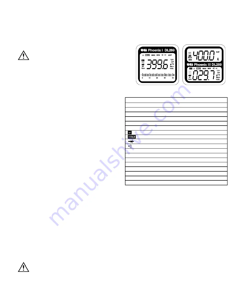
Displays and Indicators
~
AC indica t o r
=
DC indica t o r
-
I n d i cates a negative value (DC Negative Vo l t a g e )
M a x
M aximum value displayed
M i n
Minimum value displayed
A (top display)
Display is in Amps from UEi Clamp or Hook adapter
A DP (top display)
M aximum value displayed
Low battery symbol
Hold function activated
Diode function
C o n t i n u i ty function
nF / µF
Capacitance (nanofarads or microfara d s )
µ A
Microamps (1 µA is 0.000001 Amp)
H z
Fr e q u e n cy measurement
%
D u ty Cycle measurement
m V
Millivolts (1 mV is 0.001 Vo l t )
A P O
Auto power off mode active
AT
Auto range function active
O . L
Displayed if the input value exceeds selected ra n g e
Operating Instructions
Auto power off
After powering off, the meter will turn back on if you perform one of
the following; Change the range, move the position of the selector or
any other button is pressed.
To disable this function; press and hold the "
SELECT
" button while
turning the meter on. The “
APO
” indicator will now be off, indicating
that the auto power off function is not active.
Back-light / work area light
Press the “
HOLD
” button longer than two seconds to activate the
backlight/work area light. The lights automatically turn off after
10 seconds to extend battery life.
NOTE:
After activating worklight, press briefly to activate hold.
Auto / Manual Range
In auto range the meter will select the best range for the measured value,
and "
AT
" is displayed in the lower left of the display. Press the "
RA NGE
"
button to cycle through available ranges for the upper display. “
AT
” will
not be on the display when locked in a specific ra n g e .
3.
Conductor Alignment Marks:
Used to aid in the visual alignment of
a conductor when measuring inductive amperage. Greatest accura cy
is achieved when the conductor inside the clamp is centered at the
intersection of these marks.
4.
Test Lead Holder:
Used for hands-free use of one of the test probes.
5.
Hand Guard :
Used as a point of reference for the operators safety.
WARNING!
Always keep your hands and fingers behind the hand guards
when measuring current on exposed conductors. Contact may
result in serious injury.
6.
Clamp Le ve r :
Opens and closes current clamp jaw.
NOTE:
The clamp uses a high tension spring to close the jaw.
Do not allow fingers or objects to become pinched in the base
as jaw closes.
7.
MIN/M AX Button:
Activates MIN / M AX capture function, cycles
through minimum value, maximum value. Press longer than two
seconds to return to current reading.
8.
NCV/Range Button:
Activates non-contact voltage function
when meter is off. Used to select “
R a n g e
“ for the upper display
when meter is on. (NCV only available on DL279 / D L 28 9 )
9.
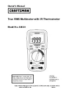
Upper Display (DL279/DL289 only):
Used to display current
when used with UEi clamp or hook adapter. Displays output from
other accessories when connected to the UEi meter.
10.
Lower Display:
Used to display input to test lead jacks. Includes
AC/DC Volts, Frequency, Resistance, Diode, Capacitance and
AC/DC microamps (µA).
11.
Select Button:
Used to choose measurement mode from
selections with multiple options such as AC or DC volts, AC or DC
µA, Resistance, Diode, Capacitance or Continuity, Temperature
in ˚F or ˚C.
NOTE:
Press and hold when turning the meter on to disable
auto power off.
12.
Hz/Duty Button:
Used to scroll through Frequency or Duty
Cycle when in the AC Voltage measurement mode.
13.
HOLD/Backlight Button:
Freezes display or activates display
backlight and work area light.
14.
Temperature Input Jack:
Input jack for k-type thermocouple
probe (DL279/DL289 only).
15.
Power/Function Selector:
Turns meter on and is used to
select the range or function.
16.
Common Te r m i n a l :
The black test lead is plugged into this terminal
to supply the ground or “low” reference for all measurements.
17.
Category Max Indicator:
Indicates maximum voltage for the
rated working category.
WARNING!
Do not exceed 1000 volts DC or AC - RMS at either the common
or multifunction input ports as measured from earth ground.
DL269/DL279/DL289-MAN
P. 2
DL279/DL289
DL269


