Introduction
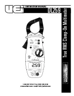
The DL259 is a hand-held, battery powered digital TRMS multimeter
with clamp-on current measuring capability. Back light and work
area light.
Features include
• True RMS
• Work light and backlit display
• 400 Amps AC
• 1000 Volts Ac and DC
• Resistance to 40 Megohms
• Continuity
• Capacitance to 10,000 microfarods
• Temperature from -40˚ to 2498˚F
• 0.1 µA DC resolution for flame safeguard circuit testing
• Time-stamped record function
• Autoranging manual override
• MIN/MAX and data hold
• 1 1/3” jaw capacity
• Three year limited warranty
Safety Notes
This meter is designed for trade professionals who know the hazards
and safety practices associated with electrical measurement. Exceeding
the specified limits of this meter is dangerous and can expose the user
to serious or possibly fatal injury.
Before using this meter, read all safety information carefully. In this
manual the word
"WARNING"
is used to indicate conditions or actions
that may pose physical hazards to the user. The word
"CAUTION"
is
used to indicate conditions or actions that may damage this instrument.
WARNING!
Higher voltages and currents require greater awareness of physical
safety hazards. Before connecting the test leads; turn off the power
to the circuit under test; set the meter to the desired function and
range; connect the test leads to the meter first, then connect to the
circuit under test. Reapply power. If an erroneous reading is
observed, disconnect power immediately and recheck all settings
and connections.
C o n t rols and Indicators
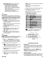
1.
Clamp:
Measure inductive AC current. Opens to 1.25" (32 mm).
NOTE:
The clamp uses a high tension spring to close the
jaw. Do not allow fingers or objects to become pinched in
the base as jaw closes.
2.
Conductor Alignment Marks:
Used to aid in the visual
alignment of a conductor when measuring inductive
amperage. Greatest accuracy is achieved when the
conductor inside the clamp is centered at the intersection
of these marks.
3.
Hand Guard:
Used as a point of reference for the
operators safety.
WARNING!
Always keep your hands and fingers behind the hand guards when
measuring current on exposed conductors. Contact may result in
serious injury.
4.
Range and Time Stamp Push-button:
Switches meter
from auto to manual ranging. Also initiates the time stamp
function when used in conjunction with MAX / MIN / R e c o r d i n g .
5.
Work Light/Hold Push-button:
Freezes the value displayed on
the digital read-out. This function does not work while recording is
in progress. Also turns on back light and work area light. Press for
2 seconds to activate the work light.
6.
MAX/MIN Push-button:
Use to cycle through recorded and
present values, and the time stamp function.
7.
Clamp Lever:
Opens and closes current clamp jaw.
8.
Mode Push-button:
Toggles the color-coded optional functions
indicated on the rotary function switch (AC to DC volts, ohms to
continuity and degrees centigrade to fahrenheit, frequency to
duty cycle).
DL259-MAN
P. 1
1
2
3
4
5
6
9
10
11
12
15
7
8
13
14


