34
1. Make sure the tool is properly and safely bolted in
place.
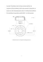
2. If the end-effector does not have a locating hole,
the orientation of the end-effector must be
archived as a file.
3. Make sure that the tool is safely constructed such
that it cannot create a hazardous situation by
dropping a part unexpectedly.
4. Pay attention to the operation specifications of
sharp end-effector tools.
5. If the installed end-effector exceeds the robotic
arm mounting surface at the zero position of the
robotic arm, a safety assessment is required for the
zero return operation.
1.3.Power Supply for the Robotic Arm
1.3.1.
Preparation before Power On
Ensure the power cable and the communication wire are properly
connected between the Control Box and the robotic arm.
Ensure the network cable or RS-485 cable is properly connected.
Ensure the power cable for the Control Box is properly connected.
Summary of Contents for 850
Page 1: ...1...
Page 72: ...72 4 The control box PC and network switch are connected by Ethernet ca ble...
Page 74: ...74 Step3 Open the Properties Step4 Open the IPV4...
Page 89: ...89 Cancel Cancel the selection Save Save the modified data Discard Discard the modified data...
Page 145: ...145 1 6 6 GPIO Control Box and End tool interface...
Page 149: ...149 1 6 7 End Effector...
Page 197: ...197 State 6 Stop Generally use studio will generate state 6 and state 6 is also a kind of stop...


