20
The xArm robotic arm system consists of a base and rotary joints, and each joint
represents a degree of freedom. From the bottom to the top, in order, Joint 1, Joint 2,
Joint 3, etc. The last joint is known as the tool side and can be used to connect end-
effector (e.g. gripper, vacuum gripper, etc).
Refer to technical specifications for joint Figures
(
See appendix-2
)
.
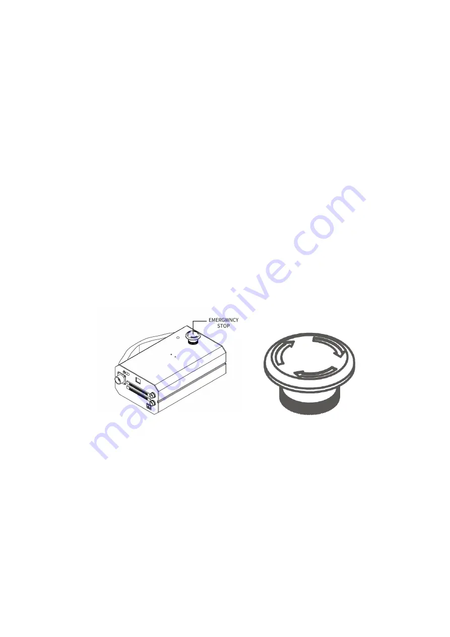
1.1.2. Emergency Stop Button
By pressing the emergency stop button of the Control Box, a command will be sent to
the Control Box for software deceleration to stop all activities of the robotic arm and
clear all the cached commands in the Control Box; the power supply for the robotic
arm will be removed within 300ms. The emergency stop should not be used as a risk
reduction measure. When an emergency occurs during the operation of the robotic
arm, users need to press the emergency stop, and the posture of the robotic arm will
slightly brake and fall. The emergency stop button is shown below:
Emergency Stop: press the emergency stop button to power off the xArm, and the
power indicator will go out.
Power-on: when the button is rotated in the direction indicated by the arrow, the
button is pulled up, the xArm power indicator lights up, and the arm is powered.
Note:
After pressing the emergency stop button, the following operations should be
performed to re-start the xArm:
1. Power up the xArm (Turn the emergency stop button in the direction of the arrow)
2. Enable the xArm (enable the servo motor)


