background image

44 


1.


  When wiring the electrical interface of the Control   

Box, the Control Box must be powered off. 


2.4.


End-Effector I/O 

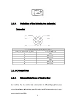
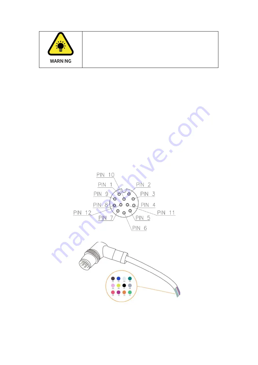
At the tool side of the robotic arm, there is an avionic socket 12-pin 

female industrial connector. This connector provides power and control 

signals for the grippers and sensors used on a particular robotic arm 

tool. Please refer to the figure below:  


Summary of Contents for xArm

Page 1: ...1...

Page 2: ...tion 13 Additional Information 13 Safety Precautions 14 xArm User Manual Hardware Section 22 1 Hardware Installation Manual 22 1 1 The Hardware Composition of xArm 22 1 2 Robot Installation 26 1 3 Pow...

Page 3: ...Hardware Preparation 73 1 2 Connect to the Robotic Arm 74 1 3 xArm Studio Homepage 82 1 4 Robotic Arm Setting 84 1 5 Live Control 138 1 6 Blockly Graphical Programming 151 1 7 Python IDE 176 1 8 Reco...

Page 4: ...rror Code and Error Handling 216 1 3 Gripper Error Code Error Handling 220 1 4 Python SDK Error Code Error Handling 222 Appendix2 Technical Specifications 224 1 1 xArm5 6 7 Common Specifications 224 1...

Page 5: ...5 Transport Storage and Handling 245 1 6 Power box placement height 245 1 7 Power Connection 245 1 8 Special Consumables 246 1 9 Stop Categories 246 1 10 Stopping Time and Stopping Distance 246 1 11 M...

Page 6: ...1302 XI1303 XI1304 XI1305 Product Information Package contains 1 Robotic Arm x 1 2 Control Box x 1 3 Power cable for the Control Box x 1 4 Power cable for the Robotic Arm x 1 5 Communication cable for...

Page 7: ...face 3 xArm end effector xArm User Manual Software Section 1 xArm Studio instructions 2 xArm motion analysis 3 Typical examples Appendix 1 xArm error reporting and handling 2 xArm technical specificat...

Page 8: ...tool other object weight in Kg the X Y Z axis indicates the position of the center of mass of the TCP relative to the default tool coordinate system with unit of mm TCP Offset Tool Center Point Offse...

Page 9: ...9 Roll Pitch Yaw The equivalent rotation matrix is X Y Z XYZ A B R R R R Note corresponds to roll corresponds to pitch corresponds to yaw...

Page 10: ...attitude representation as unit quaternion q cos phi 2 sin phi 2 x sin phi 2 y sin phi 2 z For example The vector of the rotation axis represented by the base coordinate system is 1 0 0 and the rotat...

Page 11: ...ty range is from 0 to 5 level When it is set to 0 it means that collision detection is not enabled The larger the set value the higher the collision sensitivity level and the smaller the force require...

Page 12: ...tion speed is generally calculated automatically by the system In this situation the specified speed parameter is the maximum linear speed range from 0 1000mm s 2 When the expected TCP motion only cha...

Page 13: ...col Parameter Python SDK Blockly Communication Protocol X Y Z millimeter mm millimeter mm millimeter mm Roll Pitch Yaw degree degree radian rad J1 J2 J3 J4 J5 J6 J7 degree degree radian rad TCP Speed...

Page 14: ...elevant interface instructions demonstrated in this operation manual UFACTORY devotes to providing reliable and safety information but these contents do not constitute warranties by UFACTORY UFACTORY...

Page 15: ...e a safe distance between people and xArm when interacting with the xArm Interfacing other machines and additional safety devices if defined by the risk assessment For software programming please read...

Page 16: ...ge to the device WARNING This indicates a potentially hazardous situation which if not avoided could result in death or serious damage to the device HIGH TEMPERATURE This indicates a potential hot sur...

Page 17: ...ich users should conduct self assessment of their specific problems General Alarms and Cautions 1 Make sure to use the correct installation settings in this manual for the robotic arm and all the elec...

Page 18: ...debugged 8 When the robotic arm is in an accident or abnormal operation the emergency stop switch needs to be pressed down to stop the movement and the posture of the robotic arm will slightly brake a...

Page 19: ...ic arm s joints and tools are installed properly and safely and check the status for all circuits 2 Make sure that there is enough space for the manipulator to move freely 3 Make sure that there is no...

Page 20: ...ssment of the entire collaboration system should be performed It is recommended that any equipment that may cause mechanical damage to xArm be placed outside the working range during application plann...

Page 21: ...line should be drawn to mark the range of motion of the robotic arm to let the operator acknowledge the robotic arm including its end tools such as gripper and suction cup etc operating range 4 Check...

Page 22: ...he Hardware Composition of xArm 1 1 1 Hardware Composition The composition of robotic arm hardware includes Robotic Arm Figure 2 1 Control Box Figure 2 2 Robotic Arm Signal Cable Figure 2 3 Robotic Ar...

Page 23: ...for joint Figures See appendix 2 1 1 2 Emergency Stop Button By pressing the emergency stop button of the Control Box a command will be sent to the Control Box for software deceleration to stop all ac...

Page 24: ...indicated by the arrow the button is pulled up the xArm power indicator lights up and the arm is powered Note After pressing the emergency stop button the following operations should be performed to...

Page 25: ...itch Second position switch Third position switch Emergency stop Stops the motion of the robotic arm Yes No Yes Yes Program execution Pause The buffered motion command is not cleared The robotic arm r...

Page 26: ...d on Network port indicator LAN The light is on indicating that the xArm is communicating normally Emergency stop button EMERGENCY STOP Press the button to power off the xArm Rotate the button the ROB...

Page 27: ...humid environment for a long time 2 A safety assessment is required each time installed 3 When connecting or disconnecting the arm cable make sure that the external AC is disconnected To avoid any ele...

Page 28: ...the extension of the links The figure below shows the dimensions and working range of the robotic arm When installing the robotic arm make sure the range of motion of the robotic arm is taken into ac...

Page 29: ...29 Working space of xArm7 unit mm Note The following working range diagrams are only for safety assessment...

Page 30: ...30 Working space of xArm5 and xArm6 unit mm Note The following working range diagrams are only for safety assessment...

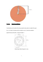
Page 31: ...stallation The robotic arm has five M5 bolts provided and can be mounted through five 5 5 holes in the base of the robotic arm It is recommended to tighten these bolts with a torque of 20N m Robot Bas...

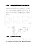
Page 32: ...unplug and plug it violently Plug the Robotic Arm Power Supply Cable and the Robotic Arm Signal Cable into the Control Box Plug the Control Box Power Cable into the AC 110V 240V interface on the Cont...

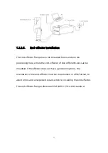
Page 33: ...e the end effector of two different sizes can be mounted If the effector does not have a positioning hole the orientation of the end effector must be documented in a file format to avoid errors and un...

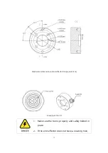
Page 34: ...34 Mechanical dimensions of end effector flange unit mm Drawing of too I O 1 Make sure the tool is properly and safely bolted in place 2 If the end effector does not have a locating hole...

Page 35: ...c arm mounting surface at the zero position of the robotic arm a safety assessment is required for the zero return operation 1 3 Power Supply for the Robotic Arm 1 3 1 Preparation before Power On Ensu...

Page 36: ...3 Rotate the emergency stop button in the direction indicated by the arrow and is pulled up at which point the xArm power indicator ROBOT PWR lights up 4 Use the xArm Studio SDK command to complete t...

Page 37: ...takes about 5 seconds to turn off the power of the control box Please do not restart the control box within 5 seconds after turning off the power supply Unplugging the power cord directly from the wal...

Page 38: ...the Robotic Arm 1 The robotic arm power supply cable connects the power port of the robotic arm and the ROBOT power port of the control box 2 The robotic arm signal cable is connected to the signal i...

Page 39: ...ther the connection between the robotic arm and the control box is secured before use The hardware protection and software protection of the control box can ensure the safety of use largely The emerge...

Page 40: ...r wire sequence Functional definition 1 GND 2 485 A Arm 3 485 B Arm 4 GND 5 485 A Tool 6 485 B Tool 2 2 DC Control Box 2 2 1 External Interfaces of Control Box Except that the DC Control Box is connec...

Page 41: ...41 DC PWR VP Connect to 24V 72V DC Input PE Connect to the control housing Leakage Protection not a must GND Connect to the ground ROBOT communication cable...

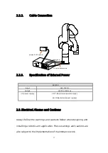
Page 42: ...max I O power supply 24V 1 8A Internal power supply 24V 3A External power supply 2 3 Electrical Alarms and Cautions Always follow the warnings and cautions below when designing and installing a roboti...

Page 43: ...ct your supplier 3 All GND connectors mentioned in this manual are only suitable for powering and transmitting signals 4 Be careful when installing the interface cable to the I O of the robotic arm 1...

Page 44: ...e powered off 2 4 End Effector I O At the tool side of the robotic arm there is an avionic socket 12 pin female industrial connector This connector provides power and control signals for the grippers...

Page 45: ...ple Tool Input 1 TI1 11 Orange Analog input 0 AI0 12 Light Green Analog input 1 AI1 The electrical specifications are as follows Parameter Min Value Typical Value Max Value Unit Supply Voltage in 24V...

Page 46: ...Sink Current 0 100 mA Current through GND 0 100 mA 2 4 1 1 Tool Digital Output Usage The following example illustrates how to use the digital output As the internal output is an open collector the res...

Page 47: ...put Voltage 0 5 30 V Logic Low Voltage 1 0 V Logic High Voltage 1 6 V Input Resistance 47k 2 4 2 1 Tool Digital Input Usage The following figure shows the connection with the simple switch 2 4 3 Tool...

Page 48: ...age protection Exceeding the limits in the electrical code may result in permanent damage to the input port 2 In current mode the pull down resistance depends on the range of the input current 2 4 3 1...

Page 49: ...non differential sensor Voltage Mode Current Mode 2 5 Control Box Electrical IO This chapter explains how to connect devices to the electrical I O outside of the control box The I Os are extremely fl...

Page 50: ...guration functions of IO see the following table Configurable Function CI0 CI7 Configurable Input DI0 DIO7 Digital Input General Input Yes Yes Stop Moving Yes No Safeguard Reset Yes No Offline Task Ye...

Page 51: ...the I O must comply with the specifications The digital I O can be powered by a internal 24V power supply or by an external power supply by configuring the power junction box In the following figure...

Page 52: ...V 24V 0V Current 0 3 A The digital I O electrical specifications are as follows Terminal Parameter Min Value Typical Value Max Value Unit Digital Output COx Current 0 100 mA COx Voltage Goes Down 0 0...

Page 53: ...see Chapter 1 All safety I Os exist in pairs redundancy and must be kept in two separate branches A single I O failure should not result in the loss of safety features There are two fixed safety input...

Page 54: ...ion Only releasing the brake No 2 5 2 1 Default Safety Configuration The robotic arm has been configured by default and can be operated without any additional safety equipment as the figure below If t...

Page 55: ...e following figure shows that two robotic arms share an emergency stop button the connection method shown in the figure below also applies to multiple robotic arms sharing an emergency stop button 2 5...

Page 56: ...le of an automatic recovery is the use of a safety pad or a safety laser scanner see the figure below 2 5 2 5 Protective Stop with Reset Button If you use a protective interface to interact with the l...

Page 57: ...unction with reset button 1 Configure CI0 as the safeguard reset in xArm Studio The specific steps are as follows Enter Settings I O Input Configure CI0 as safeguard reset Save 2 If xArm needs to resu...

Page 58: ...the form of NPN When the digital output is enabled the corresponding connector will be driven to GND When the digital output is disabled the corresponding connector will be open OC OD Users must follo...

Page 59: ...rable Input The digital input is implemented in the form of a weak pull up resistor This means that the reading of the floating input is always high Users must follow the electrical specifications set...

Page 60: ...r can be used device communication see the figure below 2 5 4 General Analog I O This type of interface can be used to set or measure voltage 0 10V going into or out of other devices For the highest a...

Page 61: ...ge Mode AIx AG Voltage 0 10 V AIx AG Resistance 10k AIx AG Resolution 12 12 bit Analog Output under Voltage Mode AOx AG Voltage 0 10 V AOx AG Current 0 20 mA AOx AG Resistance 100k AOx AG Resolution 1...

Page 62: ...sensor Connect to AI0 or AI1 2 6 Communication Interface The Control Box provides Ethernet interface as shown in the figure below 2 7 Ethernet TCP IP The control box provides a gigabit Ethernet interf...

Page 63: ...face If the connection is successful the network port indicator blinks frequently The default network segment IP address of the control box is 192 168 1 2 254 For a specific IP address please check th...

Page 64: ...e change the computer IP address to the same network segment and close the computer s network proxy To test whether the computer can communicate with the robotic arm open the command terminal and inpu...

Page 65: ...lue the greater the stroke of the gripper meaning the smaller the value the smaller the stroke of the gripper If the clamping is not tight a negative value can be set until it is tightened The speed o...

Page 66: ...2 Power off the robotic arm by pressing the emergency stop button on the control box 3 Fix the gripper on the end of the robotic arm with 2 M6 bolts 4 Connect the robotic arm and the gripper with the...

Page 67: ...nnector must be on the same side 3 When connecting the gripper and the robotic arm be sure to align the positioning holes at the ends of the gripper and the robotic arm The male pins of the connecting...

Page 68: ...en a robotic arm equipped with a gripper is used for trajectory planning it is necessary to perform a safety assessment on whether to return to the zero point or whether the operation can be performed...

Page 69: ...according to the size of the object surface and the unused suction cup needs to be sealed Note If the surface of the object is not smooth there will be air leakage from the suction cup which makes th...

Page 70: ...c arm and the vacuum gripper with the vacuum gripper connection cable Note 1 When turning on the vacuum gripper connection cable be sure to power off the robotic arm to set the emergency stop button i...

Page 71: ...m_gripper True wait False Turn on vacuum gripper arm set_vacuum_gripper False wait False Turn off vacuum gripper Note 1 Python SDK and xArm Studio provide wrapped functions that can be called to turn...

Page 72: ...and drop the code blocks of Blockly xArm Studio allows users to plan the motion trajectory for the robotic arm without programming skills Note 1 Installation systems supported by the xArm Studio clien...

Page 73: ...orkplace environment have been implemented 1 The robotic arm is fixed on the plane protective measures are in place within the range of motion 2 Check if the connection between the control box and the...

Page 74: ...ication is normal 6 Check if the robotic arm is powered and the emergency stop button is disabled If the power indicator of the robotic arm lights up it means the power is on 1 2 Connect to the Roboti...

Page 75: ...er are connected by Ethernet cable 3 PC and router are connected by wireless network and control box an d router are connected by Ethernet cable Note It is not recommended because of the delay and pac...

Page 76: ...box PC and network switch are connected by Ethernet cable 1 2 2 IP Configuration Before connecting the robotic arm with xArm Studio communication with the robotic arm make sure that the IP address of...

Page 77: ...vice has been marked on the side of the control box Therefore to successfully communicate with the control box the IPV4 network segment on the computer must be between 192 168 1 1 192 168 1 255 cannot...

Page 78: ...78 Step3 Open the Properties Step4 Open the IPV4...

Page 79: ...be the same as the IP address of the control box If not please modify the computer s IP Step6 1 2 3 Connect to the Robotic Arm There are the following two ways to communicate with the robotic arm 1 I...

Page 80: ...ox the default IP address of the device has been marked on the side of the control box 2 If you use a browser to access xArm Studio you can communicate with the robot through the following steps 1 Ope...

Page 81: ...81 1 2 4 Return to the Search Interface PC Click Tool Search to return to the search interface...

Page 82: ...ed to the robotic arm Controller IP Robot State TCP Payload Collision Sensitivity Robot Mounting and Motion Enable Robot State Error indicating that the robotic arm has not been enabled or the robot i...

Page 83: ...ector by simply drag and drop the code blocks Python IDE Python integrated development environment that uses the xArm Python SDK API directly and has ability to view the Python code generated by the B...

Page 84: ...ch the robotic arm Tools Check for Updates to check the software updates Help Help Use the drop down window to download the manuals of the robotic arm contact technical support open forums and visit G...

Page 85: ...less time it takes to reach the set speed It is recommended to be set within 20 times the maximum speed value for a smooth trajectory Position step Set the step length for fine cartesian position X Y...

Page 86: ...ensitivity Setting Collision sensitivity When the deviation of the torque detected by the joint exceeds a certain normal range during the movement of the robotic arm the robotic arm will automatically...

Page 87: ...level of Teach sensitivity is from 1 to 5 The higher the set value the smaller the force required to drag the joint in manual mode 1 4 1 4 Initial Position Setting the Initial Position of the robotic...

Page 88: ...88 1 4 2 End Effector When the end effector provided in the option is installed at the end of the xArm select the corresponding end effector...

Page 89: ...85 Gripper Robotiq 2F 140 Gripper Take the xArm Gripper as an example xArm Gripper Note 1 The opening and closing speed of the gripper can be adjusted 2 The self collision prevention model of the gri...

Page 90: ...o the TCP payload parameter of the gripper When installing other end effectors not officially provided at the end of the robotic arm please choose other 1 You can choose a 3D model cylinder cuboid tha...

Page 91: ...uation TCP Payload The load weight refers to the actual mass end effector object in Kg X Y Z axis represents the position of the centre of gravity of payload in mm this position is expressed in defaul...

Page 92: ...determine the position of TCP while Roll Pitch and Yaw determine the orientation When the specified value is zero TCP coincides with the centre point of the tool output flange 1 4 3 1 TCP Payload On t...

Page 93: ...ault payload data cannot be deleted Save Save for the newly added payload record setting the default payload and deleting the payload record Cancel Cancel saving the newly added payload record setting...

Page 94: ...nds to calculate the parameters of TCP payload In addition it is important to ensure the safety of equipment and personnel near the robotic arm Note Once the name of the new payload has been determine...

Page 95: ...are two ways to set the new TCP offset parameters as shown in the figure below 1 Manual Input When the TCP offset parameter of the end effector is known you can choose to manually input its TCP offset...

Page 96: ...ng the offset record Cancel Cancel saving the newly added offset record setting the default offset and deleting the offset record 1 4 4 I O Settings The control box of the robotic arm is equipped with...

Page 97: ...ogram only when the controller input is set as a general input otherwise it will cause a function conflict For example if CI 0 is configured as an offline task CI 0 should not be used in any program S...

Page 98: ...kly project and click to delete the project Manual Mode When set as Manual Mode the robotic arm can be dragged freely when the input signal remains low level Reduced Mode The IO is triggered and the r...

Page 99: ...er output is set as general output otherwise it will cause function conflict For example if CO 0 is configured as motion stopped CO 0 should not be used in any program Motion Stopped The system enters...

Page 100: ...rm issues a warning the output is high Collision When the robotic arm reports an error of collision the output is high Manual mode When the Manual Mode is turned on the output is high Offline task run...

Page 101: ...1 4 4 3 IO Commissioning In this interface the IO input status and IO output status of the control box can be monitored and the IO output status of the control box can be controlled by clicking the bu...

Page 102: ...mode is turned on the working range of the robotic arm in Cartesian space can be limited If the tool center point TCP of the robotic arm exceeds the set safety boundary the robotic arm will stop movi...

Page 103: ...103 1 4 5 2 Reduced Mode Reduced Mode When this mode is turned on the maximum linear speed maximum joint speed and joint range of the robotic arm in Cartesian space will be limited...

Page 104: ...ctly the robotic arm will not be able to accurately recognize the direction of gravity which will cause the robotic arm to frequently trigger a collision warning and stop motion and will also result i...

Page 105: ...method as ceiling and it is not necessary to set the angle of rotation WallUp 90 180 Indicates that the robotic arm is wall mounted and the end of the robotic arm is facing up WallDown 90 0 Indicates...

Page 106: ...ed should be in a tilt angle which ranges from 0 to 180 Rotation angle The initial position of the robotic arm and the end direction of the robotic arm to be mounted should be used as the rotation ang...

Page 107: ...the risk of rollover of the robotic arm 1 4 7 Timed Tasks Timed tasks can schedule the offline task to run at a specific time or within a time range in the future without the need for an I O triggeri...

Page 108: ...according to the system time of the control box Calibration Calibrate the system time of the control box according to the time of the connected computer New Create a new task project under which the u...

Page 109: ...time for the project has expired Delete the tasks added under the project 1 4 8 Coordinate System In this interface the user can set the coordinate offset to customize the user coordinate system X Y...

Page 110: ...user coordinate offset When creating a new base coordinate offset there are two ways to set the new base coordinate offset parameters as shown in the figure below 1 Manual Input When the base coordin...

Page 111: ...a Example When expressed in coordinate system A B is 207 0 112 180 0 0 DAC 1000mm if user want to set the world reference coordinate system to C just express the position and orientation of user coord...

Page 112: ...the robotic arm you can modify time here Note 1 The jerk affects the acceleration performance of the robotic arm In general we do not recommend modifying this parameter 2 If the robotic arm is not ena...

Page 113: ...the axis angle and R P Y Generally it is recommended to use the axis angle since the axis angle control is more intuitive The choice here determines the TCP control mode of the xArm Studio Live Contro...

Page 114: ...avoid the Blockly program from being affected by the network communication between the client and the control box during the running process which improves the running speed of the program Note After...

Page 115: ...alue of each parameter Quick access switch After enabling quick access you can quickly adjust parameters through the Quick access button in any interface of xArm Studio Quick access You can select the...

Page 116: ...116 1 4 9 3 Advanced Tools...

Page 117: ...PARAMETERS 1 or PID PARAMETERS 2 2 Then click Save In the following cases the PID parameters cannot be modified 1 If the robotic arm is not enabled the PID parameters cannot be modified 2 If an error...

Page 118: ...executing motions with payload Note 1 Changing The PID parameter can only be performed if UFACTORY technical support recommends changing the PID parameters contact technical support support ufactory c...

Page 119: ...119 Friction Identification...

Page 120: ...ion The following situation can be improved by modifying the friction identification 1 If manual mode or collision detection performance is far from satisfying Note Before friction identification plea...

Page 121: ...invalid state Otherwise the Controller Digital Output or Tool Digital Output will not be affected by the stop command Collision Rebound When this mode is turned on the robotic arm will rebound backwar...

Page 122: ...Status In this interface you can get the joint current value and joint voltage value of the robotic arm The range of the joint voltage value of the robotic arm is 0 50V The range of the joint current...

Page 123: ...s needed At this time the joint can be dragged by hand to rotate After confirming the position please re lock all the joints manually Note 1 Please ensure to hold the robotic arm by hand when unlockin...

Page 124: ...tic arm mode clicking the unlock joint button will also unlock the real joints of the robotic arm When releasing the joint brakes someone must support the robot s posture to prevent the robotic arm fr...

Page 125: ...tton communication status joint status and PID parameters And you can clear the multi turn error of the robotic arm and modify the speed threshold of the robotic arm Note This function should be compl...

Page 126: ...botic arm as a configuration file The robotic arm parameters that can be exported mainly include motion parameters TCP offset TCP payload IO settings safety boundary installation methods coordinate sy...

Page 127: ...file of a robotic arm that has been set Then click the Import Configuration button to import the configuration file to other robotic arms 2 When the control box fails and needs to be repaired you can...

Page 128: ...Please keep the new password properly If the password is lost you will need to contact UFACTORY to reset the password 1 4 10 System Settings System Settings mainly include Check Update System Informa...

Page 129: ...arm the firmware version of the arm and the xArm Studio software version Network Settings Display the IP address of the robotic arm subnet mask broadcast address and default gateway The DNS address c...

Page 130: ...formation the control box can be rebooted or the joint can be operated the degree of freedom number of axis of the current robotic arm IP address firmware version SN address and software version of th...

Page 131: ...r supply to the robotic arm Shutdown Click this button the page will go back to the Search the IP Address of the Control Box page and the control box will shut down This operation is equivalent to lon...

Page 132: ...utes Note The xArm shutdown and xArm Reboot buttons do not affect the main power supply of the control box and the power supply of the robotic arm 1 4 10 2 Software Firmware Update When updating softw...

Page 133: ...d to the Internet Note Note For detailed steps on updating xArm Studio and xArm firmware please refer to Appendix 4 xArm Software Firmware Update Method 1 4 10 3 Network Settings The IP address subnet...

Page 134: ...e IP Reset IP Steps to reset IP 1 Press the emergency stop button and turn off the power of the control box 2 Connect RI0 to GND with a cable 3 Turn on the power of the control box After hearing the s...

Page 135: ...r 192 168 1 111 in the xArm Studio search box connect the robotic arm 6 If you need to modify the IP just modify the IP in Settings System Settings Network Settings For example the modified IP is 192...

Page 136: ...136 7 Restart the control box enter your modified IP in the xArm Studio search box and connect the robotic arm...

Page 137: ...e control box no matter what IP address you modify the IP address of the control box will be automatically changed to 192 168 1 111 so after modifying the IP Be sure to unplug the cable connecting RI0...

Page 138: ...on the homepage If it is not connected please check if the robotic arm is normally turned on and check if the network connection is normal The Simulate Robot indicates that the robotic arm is connect...

Page 139: ...ear all cached commands Note The STOP button in xArm Studio is different from the one on the control box 1 The STOP button in xArm Studio allows the robotic arm to stop the current motion and clear al...

Page 140: ...ne mode Real Robot Mode Simulation Robot Mode It can reload the entire software control interface and refresh the model posture 1 5 4 Manual Mode By turning on the Manual Mode the joint can be driven...

Page 141: ...f the control box can be checked in Settings System Information 3 The SN address of the robotic arm can be checked next to the power signal interface of the base 1 5 5 Joint Motion The robotic arm con...

Page 142: ...oint and its degree Operation mode Click or for the step angles users can set the step angle in Settings Motion Settings Joint Motion Joint Step Press and hold or for continuous joint motion in a posi...

Page 143: ...responding posture in the execution process is random X Y and Z control the position of TCP in base or tool coordinate system in the unit of mm While Roll Pitch Yaw controls the TCP orientation in the...

Page 144: ...stem changes according to the changes of the joint angles Roll Pitch Yaw respectively rotates around X Y Z of the base coordinate system and the final TCP orientation is the result of the three rotati...

Page 145: ...ould be inserted and the angle that formed by the inserted point and A should be smaller than The 180 and 180 points of the Roll Pitch Yaw are coinciding in the space and the valid range is 180 so it...

Page 146: ...146 A base coordinates B TCP coordinates if no offset 1 You must check the TCP offset before recording the Cartesian position 1 5 7 Operation Mode 1 5 7 1 xArm 6 xArm 7 Operation Interface...

Page 147: ...aw under the Attitude indicates the angle value rotated under the base coordinate offset which is a description of the azimuth obtained by rotating three times around the selected coordinate system in...

Page 148: ...ettings Motion Settings Line Motion Attitude Step on the homepage Note When the real time control base coordinate system tool coordinate system is switched if the coordinate system offset is not 0 0 0...

Page 149: ...Zero Position Initial Position ZERO POSITION Indicates all joint angles values are zero Long press the button of Zero Position to return the robotic arm to the posture of Zero Position User can click...

Page 150: ...trol interface of xArm Note that the maximum speed of the live control interface is not the actual maximum motion speed of the robotic arm If you want the program to run at high speed you can add a sp...

Page 151: ...ll slow down or cause an error mechanism When a command involves displacement and rotation at the same time the time required for the displacement motion and the rotational motion depends on the one t...

Page 152: ...be converted to Python code and can be used in the xArm Python SDK library My Project xxx Click to expand to display all created items the currently open item xxx is displayed when it folds Import Pro...

Page 153: ...in the real time control interface will pop up as shown in the figure below When running the program you can observe the motion posture of the robotic arm in real time Note When the robotic arm is in...

Page 154: ...o the action panel the code execution is top down users can drag and drop the code block with the blocks attached from behind together Return to the default size and code block at centered position Zo...

Page 155: ...blank workspace of the non code block the function is mainly for all code blocks Undo Undo the previous operation Redo Restore the last undo operation Collapse Blocks Collapse all code blocks Expand B...

Page 156: ...ther files Add Comment Users can add a description to the code block which is identified by the symbol Click to open close the description pop up window as shown in the following figure External input...

Page 157: ...osition click edit Then the robotic arm will move to the current position and open the live control interface Wait true false indicating whether to wait for the execution of a command before sending t...

Page 158: ...ntains commonly used logic commands Loop Contains common loop commands such as multiple loops infinite loops and breaking loops Math Contains commands for mathematical operations Advanced Includes loc...

Page 159: ...tcp load weight XYZ Set the load of the current project refer Settings TCP Payload from the drop down list Set tcp offset X Y Z R P Y Set the end offset of the current project reference Settings TCP...

Page 160: ...sleep s After receiving this command the robotic arm will stop moving for the set time and then continue to execute the following commands It is mainly used in motion programs that need to do the con...

Page 161: ...ius Wait true false move edit Set each joint value for the joint movement with the unit of degree move arc line X Y Z Roll Pitch Yaw Radius Wait true false move edit Set the Cartesian coordinate targe...

Page 162: ...t to 360 a whole circle can be completed and it can be greater than or less than 360 Note To achieve smooth track motion you need to set Wait false move joint variable J1 J2 J3 J4 J5 J6 J7 Wait true f...

Page 163: ...s The control box has 8 digital input interfaces 8 digital output interfaces 2 analog input interfaces and 2 analog output interfaces The end tool has 2 digital input interfaces and 2 digital output i...

Page 164: ...by the robot arm with the unit of mm The digital IO is triggered as soon as the system detects that the TCP position enters a spherical area centered at X Y Z with the specified radius If the toleranc...

Page 165: ...e IO state every 100ms and uses the IO state value obtained for the first time as the initial value 2 Compare the IO state obtained the second time with the IO state obtained last time If the IO state...

Page 166: ...e strength of the gripping object initialize gripper Enable gripper object is picked release Detect whether the vacuum gripper has picked released the object If it is detected that the vacuum gripper...

Page 167: ...n true false set Set the vacuum gripper to be on and off object detection true detect whether the object is picked if not it will jump out of the entire program object detection false do not detect wh...

Page 168: ...1 If Condition 1 is true then Command 1 will be run Otherwise it will be skipped The setting method of the if else sentence 1 Click the setting button on the command block then the command block will...

Page 169: ...button the selection box is retracted if else sentence setting is completed as shown below 1 6 10 Loop forever The command contained in the loop will be executed in infinite loop repeat times do The...

Page 170: ...ion is not met it jumps out of the loop break Terminate the loop 1 6 11 Math You can use the above code block to do some complex operations such as addition subtraction multiplication and division exp...

Page 171: ...r message type Types available are information success warning error duration indicates the time interval the message is displayed the unit is in second the message indicates the content of the prompt...

Page 172: ...he command was run can be output 1 6 13 Variable Create variable New variables can be added After adding a variable there are three commands by default set the value of the variable change the value o...

Page 173: ...on without a return value to do something return Users can define a new function with a return value if return Conditional judgment sentence that can only be placed in the built in function Note 1 The...

Page 174: ...Edit Motion Coordinates Long press Move button to move the robotic arm to the position of the current command Click edit to pop up the live control interface to re edit the motion coordinates of the c...

Page 175: ...int A to point C a safety assessment must be carried out to avoid damage to peripheral facilities Due to the complexity of Cartesian commands Cartesian spatial trajectory planning needs to be solved b...

Page 176: ...y assessment before moving again to prevent collisions When the robotic arm is in certain positions there may be a situation where the linear motion is unsolvable At this time the route needs to be re...

Page 177: ...a new file Create a new folder Rename Delete the file Run the file 1 7 1 Create a New Project On this page all current project files are displayed including Blockly projects converted into Python code...

Page 178: ...sent user have to control the cached number and control the volume When awaiting commands of the control box exceed the maximum buffer amount 2048 a warning code will be returned The warning code is d...

Page 179: ...1 x2 x4 A recorded trajectory can be imported into Blockly projects Pop up live control panel Create a new recording file Manual Mode will be turned on accordingly by clicking on the button and the ro...

Page 180: ...load of the robotic arm resulting in its self motion Display recording time Stop recording Times Set playback times Speed Set playback speed Download the file Delete the file Import Project Import re...

Page 181: ...he time of instantiation That is the value of is_radian set when xArmAPI is created Here are three examples to illustrate 1 arm xArmAPI 192 168 1 226 2 arm xArmAPI 192 168 1 226 is_radian False 3 arm...

Page 182: ...tus Analysis Joint Motion to achieve the point to point motion of joint space unit degree radian the speed between each command is discontinuous Linear Motion to achieve linear motion between Cartesia...

Page 183: ...before 1 4 0 is 100Hz If the frequency of sending commands exceeds 250Hz the redundant commands will be lost The xArm Python SDK interface function we provide also reserves the speed acceleration and...

Page 184: ...ation and time settings but they will not work at present The suggested way of use If you want to plan your track you can use this command to issue a smoothed track point with interpolation at a certa...

Page 185: ...The operator should have safety knowledge on emergencies 4 When planning the path for the robotic arm the risk assessment must be done and the operator should be cautious 2 1 2 Analysis of Robotic Ar...

Page 186: ...s own or third party such as ROS Moveit planning algorithm Do not use this mode if users cannot implement trajectory planning and inverse kinematics by themselves Mode 2 Joint teaching mode In this mo...

Page 187: ...mally respond to and execute motion commands If the robotic arm recovers from an error power outage or stop state state 4 remember to set the state to 0 before continuing to send motion commands Other...

Page 188: ...ic arm is set to pause state and the motion commands buffer may not be empty State 4 Stopping This state is the state entered by default upon power on Stop and on commands can be executed until state...

Page 189: ...joint movement in s Set joint acceleration s Set the acceleration of joint motion in s2 move joint J1 J2 J3 J4 J5 J6 J7 Radius Set each joint angle for the joint movement the unit is Wait true false i...

Page 190: ...scribed in Table 2 1 Table 2 1 Description of set_servo_angle set_servo_angle description set joint angle for joint motion parameter servo_id joint ID 1 7 None or 8 means all joints a 1 Number of axes...

Page 191: ...an If is_radian False the unit of roll pitch yaw is degree wait If wait True wait for the current commands to finish before sending the next commands If wait False send the next commands directly mvti...

Page 192: ...ption Radius 60 Radius 60 in the move joint command refers to setting the radius of the transition arc R 60mm which is used to achieve a smooth transition of the arc in a joint motion The parameters o...

Page 193: ...ansition at the turn it will be a sharp turn with no deceleration as shown in the figure below 3 Radius 0 There is no arc transition at the turn this speed will not be continuous between this and next...

Page 194: ...r motion between Cartesian coordinates unit mm the speed is not continuous between each command Users can control the motion of the robotic arm based on the base coordinate system and TCP coordinate s...

Page 195: ...relationship between the joint space and Cartesian space the joint motion may exceed its maximum speed and acceleration limits Blockly example Set TCP speed mm s Set the speed of the linear motion in...

Page 196: ...ibed in Table 2 2 Table 2 2 set_position description set_position Description Sets the Cartesian coordinate value of the linear motion Parameter x coordinate x unit mm y coordinate y unit mm z coordin...

Page 197: ...mands if wait False send the next commands directly Note If it is xArm5 roll and pitch must be set to roll 180 and pitch 0 2 2 2 2 Arc Linear Motion Characteristics of Arc Linear Motion Arc linear mot...

Page 198: ...straight motion The parameters of Radius can be set as Radius 0 Radius 0 Radius 1 different parameters correspond to different trajectories 4 Radius 0 For example setting Radius 5 the turning trajecto...

Page 199: ...this and next motion as shown in the figure below speed will decelerate to 0 at point B before moving to C Note Radius 0 cannot realize continuous motion If you need to plan a continuous movement of t...

Page 200: ...time interface is described in Table 2 3 Table 2 3 set_pause_time description set_pause_time Description Set the robotic arm pause time Parameter sltime pause time unit second s wait whether to wait d...

Page 201: ...degree center angle 60 the motion trajectory of the robotic arm is 2 The center angle 360 the movement track of the robotic arm is a complete circle 3 If you want to draw multiple circles continuousl...

Page 202: ...trajectory center angle Indicates the degree of the circle When it is set to 360 a whole circle can be completed and it can be greater than or less than 360 Note To achieve smooth motion you need to s...

Page 203: ...on 300 0 0 0 400 0 0 0 90 0 180 0 speed 300 mvacc 2000 radius 1 0 wait True move_circle 350 0 50 0 400 0 180 0 90 0 0 0 350 0 50 0 400 0 180 0 90 0 0 0 1000 0 speed 300 mvacc 2000 wait True set_servo_...

Page 204: ...nds to be sent before sending the next commands If wait False send the next commands directly 2 3 xArm5 Motion Characteristics Cartesian space The movement of xArm5 is relatively special Due to the st...

Page 205: ...f J4 equal to J2 angle J3 angle 2 4 Singularity 1 Concept Singularities occur when the axes of any two joints of a robotic arm are on the same straight line At the singularity point the robot s degree...

Page 206: ...s cannot be explicitly translated into joint motions of each axis When the robot performs motion planning linear circular etc excluding joint movements near the singularity point it will stop to avoid...

Page 207: ...ion and attitude of the robot and re plan the path to the target point Note It is important to consider the cylindrical volume directly above and directly below the base of the robotic arm when a moun...

Page 208: ...download address of the Blockly program The use of xArm vacuum gripper blockly The role of this program execute this program to control the vacuum gripper to suck the target object at the specified po...

Page 209: ...cuum gripper has not yet picked released the object it will also jump out of the command and execute the next command set xarm vacuum gripper ON OFF object detection true false set Set the vacuum grip...

Page 210: ...nd then place the target object at the target position 3 3 The Use of the Digital IO The download address of the Blockly program The use of the digital IO blockly The role of this program If you need...

Page 211: ...Blockly program Cyclic Motion Count blockly Counter counts Cyclic motion count By adding Counter plus each time the command is run the counter of the Control Box will be incremented by 1 It can be us...

Page 212: ...ecause wait false the commands will be sent continuously until the control box buffer is full According to the above example the number of cycles of the robotic arm is 10 times When wait false the i c...

Page 213: ...the counter for counting Appendix Appendix1 Error Reporting and Handling 1 1 Joints Error Message and Error Handling Error processing method Re power on the steps are as follows 1 Turn the emergency s...

Page 214: ...art the xArm with the Emergency Stop Button on the xArm Control Box S11 Joint Overcurrent Please restart the xArm with the Emergency Stop Button on the xArm Control Box S12 Joint Overspeed Please rest...

Page 215: ...viation Please check whether the xArm movement is blocked whether the payload exceeds the rated payload of xArm and whether the acceleration value is too large S26 Joint N Positive Overrun Please chec...

Page 216: ...with the Emergency Stop Button on the xArm Control Box For alarm codes that are not listed in the above table Power on again If the problem remains unsolved after power on off for multiple times plea...

Page 217: ...Enable Robot C11 C17 Power on again C19 End Module Communication Error Please check whether gripper is installed and the baud rate setting is correct C21 Kinematic Error Please re plan the path C22 Se...

Page 218: ...e TCP payload parameters set in your program match the actual payload 5 Reduce the motion speed of the robotic arm 6 Go to Settings Motion Sensitivity Settings to lower the collision sensitivity C32 T...

Page 219: ...this command is 0 1 2 C52 Six axis Force Torque Sensor Zero Setting Error Please check the sensor communication wiring and whether the power is normal C53 Six axis Force Torque Sensor Overload Please...

Page 220: ...ower on the robotic arm as an error handling the steps are as follows all the following steps are needed 1 Re powering the robotic arm via the emergency stop button on the control box 2 Enable the rob...

Page 221: ...er G15 Gripper EEPROM Read and Write Error Please click OK to re enable the Gripper G20 Gripper Driver IC Hardware Error Please click OK to re enable the Gripper G21 Gripper Driver IC Initialization E...

Page 222: ...not ready Please check whether the robot is enabled and the state is set correctly A 1 xArm is disconnect or not connect Please check the network A1 There are errors that have not been cleared Please...

Page 223: ...the status of the end effector A102 There are errors in the end effector A103 The end effector is not enabled For alarm codes that are not listed in the above table enable the robotic arm and gripper...

Page 224: ...er Supply 24 V DC 16 5 A ISO Class Cleanroom 5 Robotic Arm Mounting Any Programming xArm Studio Python C ROS Robotic Arm Communication Protocol Modbus TCP End effector I O Interface 2 Digital inputs 2...

Page 225: ...ing Range 84mm Maximum Clamping Force 30N Weight g 802g Communication Mode RS 485 Communication Protocol Modbus RTU Programmable Gripping Parameters Position Speed Feedback Position Vacuum Gripper Rat...

Page 226: ...operation is needed 1 2 xArm 5 Specifications Joint Range 1 5 360 2 118 120 3 225 11 4 97 180 Payload 3kg Degrees of Freedom 5 Weight robotic arm only 11 2kg Robot Joints Robot Zero Attitude Joint Rot...

Page 227: ...Joint Range 1 4 6 360 2 118 120 3 225 11 5 97 180 Payload 5kg Degrees of Freedom 6 Repeatability 0 1mm Weight robotic arm only 12 2kg Robot Joints Robot Zero Attitude Joint Rotating Direction 1 4 xArm...

Page 228: ...228 Joint Range 2 118 120 4 11 225 6 97 180 Payload 3 5kg Degrees of Freedom 7 Weight robotic arm only 13 7kg Robot Joints Robot Zero Attitude Joint Rotating Direction...

Page 229: ...ration 6 How to use PLC to control xArm 7 Guide to control xArm by tablet 8 Kinematic and Dynamic Parameters of xArm Series 9 The Proper Way to Power DC Control Box 10 How to get the joint current tor...

Page 230: ...arm network setting Notes 1 It is recommended to update the xArm firmware and xArm Studio at the same time 2 After updating please download the latest xArm User Manual and xArm Developer Manual from...

Page 231: ...The download link https github com xArm Developer 1 When you use the following network setting methods please use xarm tool gui tool to update xArm Studio and xArm firmware online The control box is d...

Page 232: ...lation package run the xarm tool gui program that matches your PC s operating system select the type of robotic arm and enter the IP address of the xArm control box then click Connect 3 After successf...

Page 233: ...n is completed the console of the xarm tool gui will display Install firmware success or Install Studio success Finally click Reboot Control Box and wait for the control box to reboot the reboot usual...

Page 234: ...you use the following network setting methods please use xarm tool gui tool to update xArm Studio and xArm firmware offline The control box is directly connected to the PC The PC is not connected to t...

Page 235: ...tallation package using a USB drive copy it to the PC connected to the xArm control box After decompressing the installation package run the xarm tool gui program that matches your PC s operating syst...

Page 236: ...success or Install Studio success Finally click Reboot Control Box and wait for the control box to reboot the reboot usually takes about 2 3 minutes 3 When you use the following network setting method...

Page 237: ...237 1 The control box PC and router are connected by ethernet cable The control box PC and network switch are connected by ethernet cable...

Page 238: ...box and router are connected by ethernet Cable Click Settings on the xArm Studio homepage enter System Settings Check Update click Update Wait for the system to prompt to restart and then click Resta...

Page 239: ...vide a dedicated xarm tool gui installation package Appendix5 Maintenance and Inspection 1 Long term placement If the robotic arm is not used for a long time 6 months you need to power on the robotic...

Page 240: ...When cleaning the carbon fiber surface be careful not to let the liquid penetrate the joints Appendix6 Repair 1 Repair work must only be done by UFACTORY After repair work checks must be done to ensur...

Page 241: ...will check the product warranty status according to the after sales policy 4 Generally the process takes around 1 2 weeks except for shipment Note 1 Please keep the original packaging materials of th...

Page 242: ...242 section 1 4 9 2 Advanced Tool Configuration File Appendix7 Product Information 1 1 Product Mark Robotic Arm Control Box...

Page 243: ...EMC IEC 61000 6 2 2005 IEC 61000 6 4 A1 2010 EN 61000 6 2 2005 2004 108 EC EN 61000 6 4 A1 2011 2004 108 EC Electromagnetic compatibility EMC Part 6 2 Generic standards Immunity for industrial enviro...

Page 244: ...equirements for safety related functions Conforming to this standard ensures that the safety functions of xArm robots provide safety even if other equipment exceeds the EMC emission limits defined in...

Page 245: ...securely tightened at the base of the robot The controller box shall be lifted by the handle Save the packaging material in a dry place you may need to pack down and move the robot in the future 1 6 P...

Page 246: ...ut of the Control Box Performs a Stop Category 1 Emergency Stop Button of the Three Position Enabling Device Performs a Stop Category 1 Three Position Enabling Device Performs a Stop Category 2 Safegu...

Page 247: ...llowed a vertical trajectory i e the axes of rotation were parallel to the ground and the stop was performed while the robot was moving downwards Stopping Distance rad Stopping time ms Joint 1 0 62 52...

Page 248: ...ravity 1 13 Specifications Robotic Arm Model XI1300 Joint Range 1 4 6 360 2 118 120 3 225 11 5 97 180 Payload 5kg Maximum Reach 700mm Degrees of Freedom 6 Repeatability 0 1mm Maximum Joint Speed 180 s...

Page 249: ...ication Protocol Modbus TCP Weight 3 9kg Operating Temperature 0 50 C Humidity 25 85 non condensing Short Circuit Rating 50A Input 1PHASE AC 100 240V 47 63HZ 550Wmax Manufacturer UFactory Technology C...

Reviews: