S9180-32X Hardware Installation Guide | 21
12
Cable Connections
Connecting the USB Cable
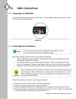
Connect the USB 2.0 A Type plug (male connector) into the USB port (female connector) located
on the front panel of the switch.
Figure 28.
Connecting the Transceivers
To prevent over tightening and damaging the optic fibers, it is not
recommended to use tie wraps with optical cables.
Read the following guidelines before connecting the transceiver:
•
Before installing the switch, take into consideration rack space requirements for cable
management and plan accordingly.
•
It is recommended to use hook-and-loop style straps to secure and organize the cables.
•
For easier management, label each fiber-optic cable and record its respective connection.
•
Maintain a clear line of sight to the port LEDs by routing the cables away from the LEDs.
Before connecting anything (cables, transceivers, etc.) to the switch, please ensure
to discharge any static electricity that may have built up during handling. It is also
recommended the cabling be done by a professional who is grounded, such as by
wearing an ESD wrist strap.
Please follow the steps below for connecting a transceiver.
1.
Remove the new transceiver from its protective packaging.
2.
Remove the protective plug from the transceiver port.
3.
Place the bail (wire handle) in the unlocked position and align the transceiver with the port.
4.
Slide the transceiver into the port and use gentle pressure to secure it in place. An audible click
can be heard when the transceiver is secured in the port.


