background image

INSTALLATION

7

UFO


LIGHTING

MOUNTING


THE


ENCLOSURE

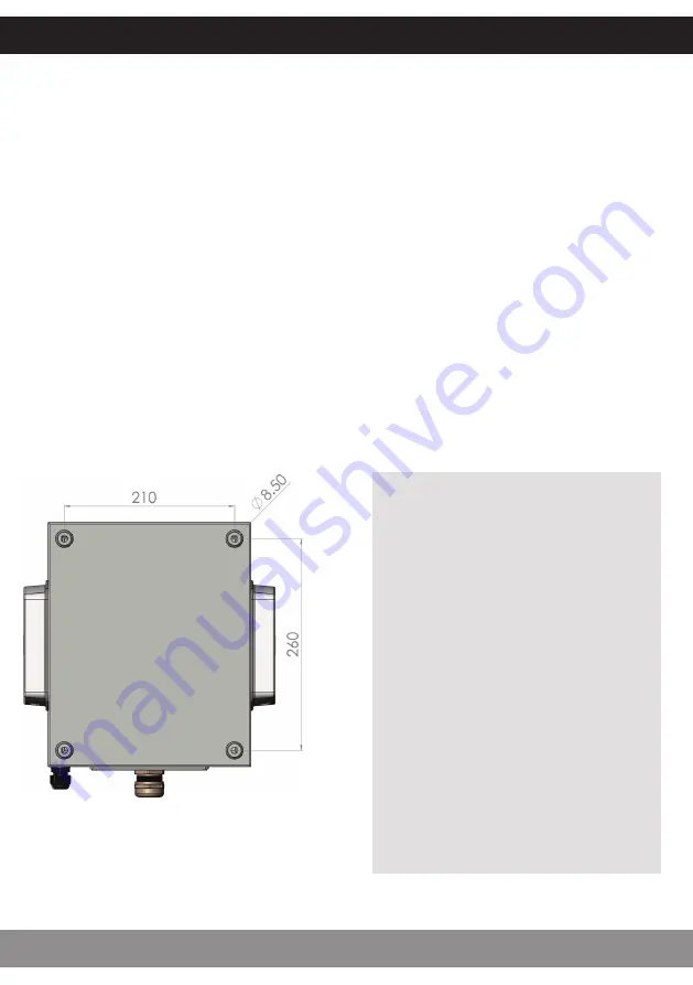
The diagram below shows the mounting hole positions on the rear face of the enclosure. 
 
Mount as follows: 
 
1. Support the enclosure against the mounting surface and use a spirit level to ensure 
that it is level. As detailed opposite, the glands must be facing downwards. 
 
2. Mark the 4 mounting hole positions and remove the enclosure from the surface. 
 
3. Choose appropriate fixings for the surface that the enclosure is being mounted to. Note 
that unless UFO are installing the unit then we do not supply fixings. This is due to the 
large variance of surface types the enclosure may be mounted to.  
 
4. Follow the instructions for the chosen fixings and use them to secure the enclosure to 
the mounting surface.

Outside/Rear 
of enclosure

MOUNTING


THE


REMOTE


PSU

For remote DC enclosures (suffix 
DC) the remote PSU should be 
mounted in a suitable location 
considering the following to 
minimise voltage drop between 
PSU and enclosure: 
 
1. Distance between PSU and 
enclosure.  
2. Size (AWG) of interconnecting DC 
cable between PSU and enclosure.  
 
NOTE: Maximum distance of 10m of 
interconnecting cable based on a 
minimum cable size of 16AWG. 

Summary of Contents for IP-01

Page 1: ...PRODUCT USER GUIDE IP 01 Weatherproof Enclosure PLEASE READ THIS USER GUIDE BEFORE INSTALLING OPERATING OR PERFORMING MAINTENANCE ON THE ENCLOSURE Rev C1...

Page 2: ...person familiar with the construction and operation of the product and the hazards involved When used in the USA or Canada cables connected to this enclosure must be UL listed and not only suitable f...

Page 3: ...the customer For the USA and Canada if supplied by the customer the PSU must be UL listed and not only suitable in terms of correct voltage and wattage but also suitable for the environment location i...

Page 4: ...INTRODUCTION 4 FIGURE 2 AC POWERED VARIANT IP 01 WEATHERPROOF ENCLOSURE USER GUIDE...

Page 5: ...rce Model Power Variant Max Wattage UFO IP01 MIC1000 AC MicroLED 1000 240VAC 50Hz 5W UFO IP01 MIC1000 DC MicroLED 1000 12V DC 5W UFO IP01 MIC4000 AC MicroLED 4000 240VAC 50Hz 5W UFO IP01 MIC4000 DC Mi...

Page 6: ...ust be located out of direct sunlight and there must be a minimum of 300mm 12 of space around all sides to allow for air circulation and to prevent overheating Mounting the enclosure in any other way...

Page 7: ...te that unless UFO are installing the unit then we do not supply fixings This is due to the large variance of surface types the enclosure may be mounted to 4 Follow the instructions for the chosen fix...

Page 8: ...eal Do not overtighten the nylon gland Never run the luminaire with the fibre optic harness out of the aperture Loosen the gland for the DMX cables and feed the cables carefully through the gland leav...

Page 9: ...s and feed the cables carefully through the gland leaving sufficient slack inside the enclosure to reach the back of the light source Tighten the gland and fit RJ45 connectors to the cables as detaile...

Page 10: ...cator on Light source not connected correctly Refer to Troubleshooting section in light source user guide Light source not set up correctly Refer to Operation section in light source user guide DC enc...

Page 11: ...lity for any loss or damage that occurs due to incorrect mounting Port Connector Size 30mm Fibre Type Glass or PMMA Material Finish Sheet Steel RAL7035 Overall Dimensions 300mm x 250mm x 155mm 11 8 x...

Page 12: ...bH Andreasstra e 20 93059 Regensburg Deutschland 49 0 9491 955880 www ufo licht de Universal Fiber Optics USA LLC 1749 Northgate Blvd Sarasota FL34234 USA 941 343 8115 www fiberopticlighting com Unive...

Reviews: