background image

CONNECTIONS

There are 3 connections required – the fibre port, the mains supply cable and, optionally, the 
DMX control cable. The fibre port should be connected first. Connect and secure the fibre optic 
connector into the 30mm diameter collar and secure using the M5 locking screw. 
 
Connect the PSU to the DC input jack socket on the illuminator, and connect the IEC plug to the 
PSU. Plug the mains plug into the electrical supply socket.  Switch on power. The LED Indicator 
will illuminate and the illuminator is ready for use. 
 
If no light is produced consult the troubleshooting section. 

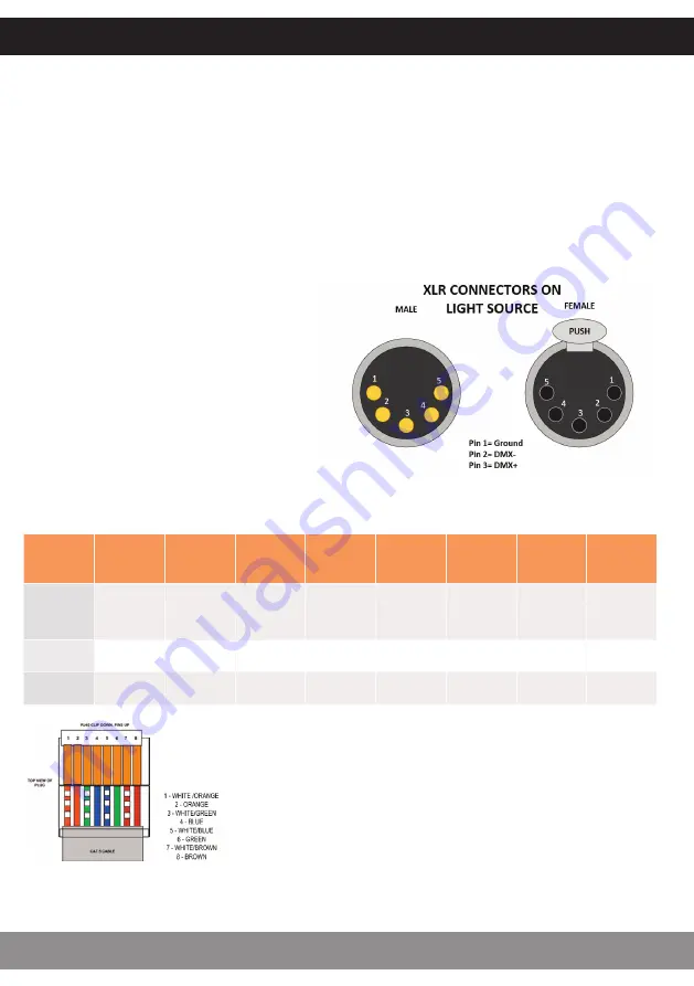
As well as the standard XLR connectors for DMX connection, the Nova is also fitted with RJ45 
connectors which also offer DMX capability. Details of these are below:

Pin No:

1

2

3

4

5

6

7

8

Color

White 

Orange

Orange

White 
Green

Blue

White 

Blue

Green

White 

Brown

Brown

Func

ti

on

DMX+

DMX

­

Spare

Spare

Spare

Spare

Ground

Ground

XLR =

Pin 3

Pin 2

­

­

­

­

Pin 1

Pin 1

Note:


It is recommended that a 120ohm terminating resistor be 
connected across DMX+ and DMX- on the last illuminator 
on the DMX universe or cable run. 
 
Nova Master Slave function will only work when both 
Master Nova and Slave Nova is set to address 001.

If DMX control is required, connect up 
the DMX control cables to the XLR 
sockets on the rear of the illuminator. 
The pin out details for the plugs are 
shown right.

INSTALLATION

NOVA


USER


GUIDE

4

Summary of Contents for NOVA DMX

Page 1: ...PRODUCT USER GUIDE Nova Illuminator PLEASE READ THIS USER GUIDE BEFORE INSTALLING OPERATING OR PERFORMING MAINTENANCE ON THE ILLUMINATOR UNIT E357731 Rev C2...

Page 2: ...ble The LED array in this illuminator is not replaceable When it reaches end of life the whole unit must be replaced Type Y Attachment If the external flexible cable or cord of this luminaire or assoc...

Page 3: ...e refer to the fitting instructions supplied with it INSTALLATION 3 UFO LIGHTING POWER SUPPLY REQUIREMENTS The Nova illuminator is powered from a 24V DC desk top power supply unit This PSU is an IEC i...

Page 4: ...l as the standard XLR connectors for DMX connection the Nova is also fitted with RJ45 connectors which also offer DMX capability Details of these are below Pin No 1 2 3 4 5 6 7 8 Color White Orange Or...

Page 5: ...ns are available in Master mode Note For Master Slave to operate both master slave units must be set to address 001 only STANDALONE REMOTE MODE Again in this mode the illuminator set to Remote can be...

Page 6: ...fect the operation of your remote control If you do accidentally touch any of the buttons remove the batteries and start again Once the batteries are inserted do not use the remote control for 3 secon...

Page 7: ...or then replace and touch button 5 within 3 seconds the illuminator will blink twice slowly indicating that the Remote Controller is matched to the illuminator Once the remote is matched follow the pr...

Page 8: ...adjustable Touch color ring then mode to enter this mode at any time 2 White and col ors mixed Adjustable Non adjustable Color ring control Touch color ring to enter this mode at any time 3 All color...

Page 9: ...range sensitivity is reducing and also to record dead areas within the remote control units range due to RF obstructions and or RF interference Note Where a illuminator has more than one remote contr...

Page 10: ...PROGRAMMING OPERATION NOVA USER GUIDE 10...

Page 11: ...PROGRAMMING OPERATION 11 UFO LIGHTING...

Page 12: ...time display timer and then fade slowly to next color 12 Fade color change between colors 2 3 4 5 6 7 Display color for adjustable time display timer and then fade slowly to next color 13 Fade color c...

Page 13: ...e Wheel 0 5 o 6 255 slow to fast 6 LED and Fan 0 250 on 251 255 o Note the fan is controlled by a temperature circuit on the LED driver PCB switching the fan on and off to optimise LED Junction temper...

Page 14: ...iled Replace remote illuminator receiver failed Replace illuminator Not responding to DMX no rotating symbol on LCD display illuminator not in DMX mode Check mode programming and set to DMX DMX addres...

Page 15: ...25 C Red 615nm 700lm Green 530nm 1160lm Blue 460nm 315lm White 6500K 1435lm Control Functionality DMX manual dimming DMX Functionality User addressable to 512 DMX Channels 6 channels Color Change Fun...

Page 16: ...dsfactory AG Gutenbergstra e 1 85737 Munchen Deutschland 49 0 9491 955880 www ufo licht de Universal Fiber Optics USA LLC 1749 Northgate Blvd Sarasota FL34234 USA 941 343 8115 www fiberopticlighting c...

Reviews: