background image

5

UFO LIGHTING

INSTALLATION

5

UFO LIGHTING

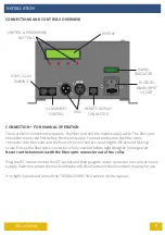
CONNECTIONS AND CONTROLS OVERVIEW

0-10V / 1-10V

DIMMING

0-10V WHEEL

CONTROL

DMX

REMOTE DISPLAY

CONNECTOR

MAINS

INDICATOR

DISPLAY

CONTROL & PROGRAMME

BUTTONS

FUSED IEC

MAINS INPUT

SOCKET

CONNECTION

FOR MANUAL OPERATION

There are two connections required – the fiber port and the mains supply cable. The fiber port
should be connected first before the mains supply. Connect and secure the fiber optic 
connector into the collar and the front of the unit and secure using the M5 knurled locking
screw. Ensure the fiber optic connector is fully inserted before tightening the locking screw.

Never run the luminaire with the fiber optic connector out of the collar.

Plug the IEC connector into the IEC socket and then plug the mains connector into a local mains
supply. Switch on power the mains indicator will illuminate and the illuminator is ready for use. 

If no light is produced consult the TROUBLESHOOTING section in this manual.

Summary of Contents for Quasar UFOQUA3080-A

Page 1: ...UFO LIGHTING FIBER OPTIC LED LIGHTING SYSTEMS REVISION B3 QUASAR ILLUMINATOR RANGE USER GUIDE PLEASE READ THIS USER GUIDE BEFORE INSTALLING OPERATING OR PERFORMING MAINTENANCE ON THE ILLUMINATOR UNIT...

Page 2: ...rative Wheel 57 5700K CF Color Segment Decorative Wheel with Separate Control Feed 65 6500K MODELS COVERED BY THIS USER GUIDE UFOQUA3080 A UFOQUA4080 A UFOQUA5080 A UFOQUA5780 A UFOQUA6580 A UFOQUA308...

Page 3: ...person to avoid a hazard Location Do not locate this illuminator closer than 200mm 8 from any flammable surface Clearance Ventilation It is imperative that a gap of 200mm 8 is left around the unit Thi...

Page 4: ...ce receiving Dimming only for two white light models Two versions for white light only standard and emergency light Emergency light version reverts to maximum light output when mains power to the 0 10...

Page 5: ...re the mains supply Connect and secure the fiber optic connector into the collar and the front of the unit and secure using the M5 knurled locking screw Ensure the fiber optic connector is fully inser...

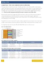
Page 6: ...e up and connect the RJ45 plug to the Quasar end of the dimmer cable and plug into connector A the left hand RJ45 on the rear of the luminaire using pin outs as detailed below Only the left hand RJ45...

Page 7: ...onnector into a local mains supply Switch on power the mains indicator will light and the illuminator is ready for use If no light is produced consult the TROUBLESHOOTING section in this manual REMOTE...

Page 8: ...l system is powered up and supplying a control voltage Plug the IEC connector into the IEC socket and then plug the mains connector into a local mains supply Switch on power the mains indicator will i...

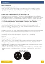
Page 9: ...tightening the locking screw Never run the luminaire with the fiber optic connector out of the collar Wire up using the DMX cable from the DMX control system Solder the cables to the 3 pin XLR male an...

Page 10: ...with the fiber optic connector out of the collar Wire up using the DMX cable linked from the Master to each Slave Quasar Solder the cables to the 3 pin XLR male and female plug and socket using pin ou...

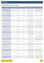
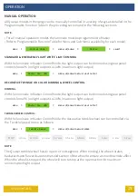
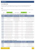
Page 11: ...iled below MENU SCROLL DOWN SELECT ENTER SCROLL UP All Quasar models can be manually controlled as detailed in the following section WHITE LIGHT MODELS On power up the display will momentarily display...

Page 12: ...Wheel Once the luminaire is powered up user controlled manual functions and all programming features are available via the four rear panel pushbuttons as detailed in the figure above and the following...

Page 13: ...rgency White Light E Control Mode 0 10V Allows 0 10V control of dimming to emergency values Press enter to select Emergency White Light E Dim Level None If set to Master allows manual dimming of light...

Page 14: ...l C Reset Options None When set to Master allows unit to be manually reset Use buttons to display YES or NO Press enter to select Decorative Color Wheel C Select Program PA01 to PA10 If set to Master...

Page 15: ...IGHT OUTPUT Master Dim 90 DECORATIVE TWINKLE OR COLOR DIMMING WHEEL CONTROL With the luminaire in Master Control Mode the light output can be dimmed using rear panel controls from 0 no light output to...

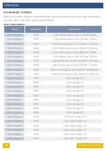
Page 16: ...to color 60 color 6 Orange Select Program PA08 Color wheel snap to color 70 color 7 Violet Select Program PA09 Color wheel snap to color 80 color 8 Magenta Select Program PA10 Color wheel snap to colo...

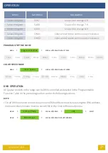
Page 17: ...c 1 min 2 min 5 min 10 min 30 min 60 min COLOR SPEED MODE MENU SCROLL UP DOWN TO ADJUST SPEED Color Speed 0 1 RPM 0 2 RPM 0 3 RPM 0 4 RPM 0 5 RPM 0 6 RPM 0 8 RPM 1 RPM 2 RPM 4 RPM DMX OPERATION All Qu...

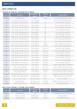
Page 18: ...Orange displayed 02 Color wheel control snap to 6 Color Wheel 123 130 Color 6 Pink displayed 02 Color wheel control snap to 5 Color Wheel 131 138 Color 5 Red displayed 02 Color wheel control snap to...

Page 19: ...Color wheel control snap to 4 Color Wheel 1 5 Color 4 Yellow displayed 02 Color wheel control snap to 5 Color Wheel 2 Color 5 Red displayed 02 Color wheel control snap to 6 Color Wheel 2 5 Color 6 Pin...

Page 20: ...esired E ect 01 LED Dimming Standard White Light 1 10 Min 10 to max light output 1 CHANNEL 1 10V DIMMING STANDARD WHITE LIGHT MASTER SLAVE OPERATION All Quasar models in the range can be Master Slave...

Page 21: ...MAINTENANCE MAINTENANCE LOG Date Maintenance Undertaken Note A record of all maintenance MUST be kept in the table above indicating what maintenance was undertaken and when This MUST be dated for war...

Page 22: ...ning Unit in DMX control mode but channel 5 value set 200 Reduce channel 5 DMX controller value to 0 Failed internal component Contact UFO MANUAL MODELS No manual control over dimming or decortative w...

Page 23: ...for a current sink type 1 10V MODELS Dim level changes with remote dimming light out put range inaccurate or reduced Incompatible current sink dimmer Contact UFO 0 10V MODELS No control over dimming o...

Page 24: ...1 10V Remote Manual Dimming Separate Feed DMX Decorative Models User addressable 5 channels 0 255 White Light Models 2 channels dimming unit control LED Life 50 000 hours typical Operating Environment...

Page 25: ...25 UFO LIGHTING NOTES...

Page 26: ...26 UFO LIGHTING NOTES...

Page 27: ...27 UFO LIGHTING NOTES...

Page 28: ...ited Kingdom t 44 0 1890 883416 www ufo lighting Universal Fiber Optic Lighting USA LLC 6119A Clark Center Avenue Sarasota FL34238 United States t 1 941 343 8115 www fiberopticlighting com Made in the...

Reviews: