background image

Instructions for use (rev 011221) 

e.ON sinter fast + 


UGIN DENTAIRE 


3


B.


INSTRUCTIONS FOR USE


1.


SAFETY INSTRUCTIONS 

1.1.


USE 

e.ON sinter fast + is a sintering furnace for production of many elements in conventional cycle and the 
rapid production of some elements for Zirconium oxide (ZrO

2

) dental restorations. This furnace has to be 

operated only by dental professionals. e.ON  sinter fast + have to be used in the conditions and for the 
intended use in this manual.

 Any other use that will be made of it is considered inappropriate. In this case, 

the manufacturer declines all liability and immediately cancels the equipment warranty. 

According  to  the product’s instructions and  functionalities, 

it is  imperative to  read carefully  the  manual 

before furnace installation and operations. 

Retain the manual for future reference. 


1.2.


SAFETY INSTRUCTIONS 

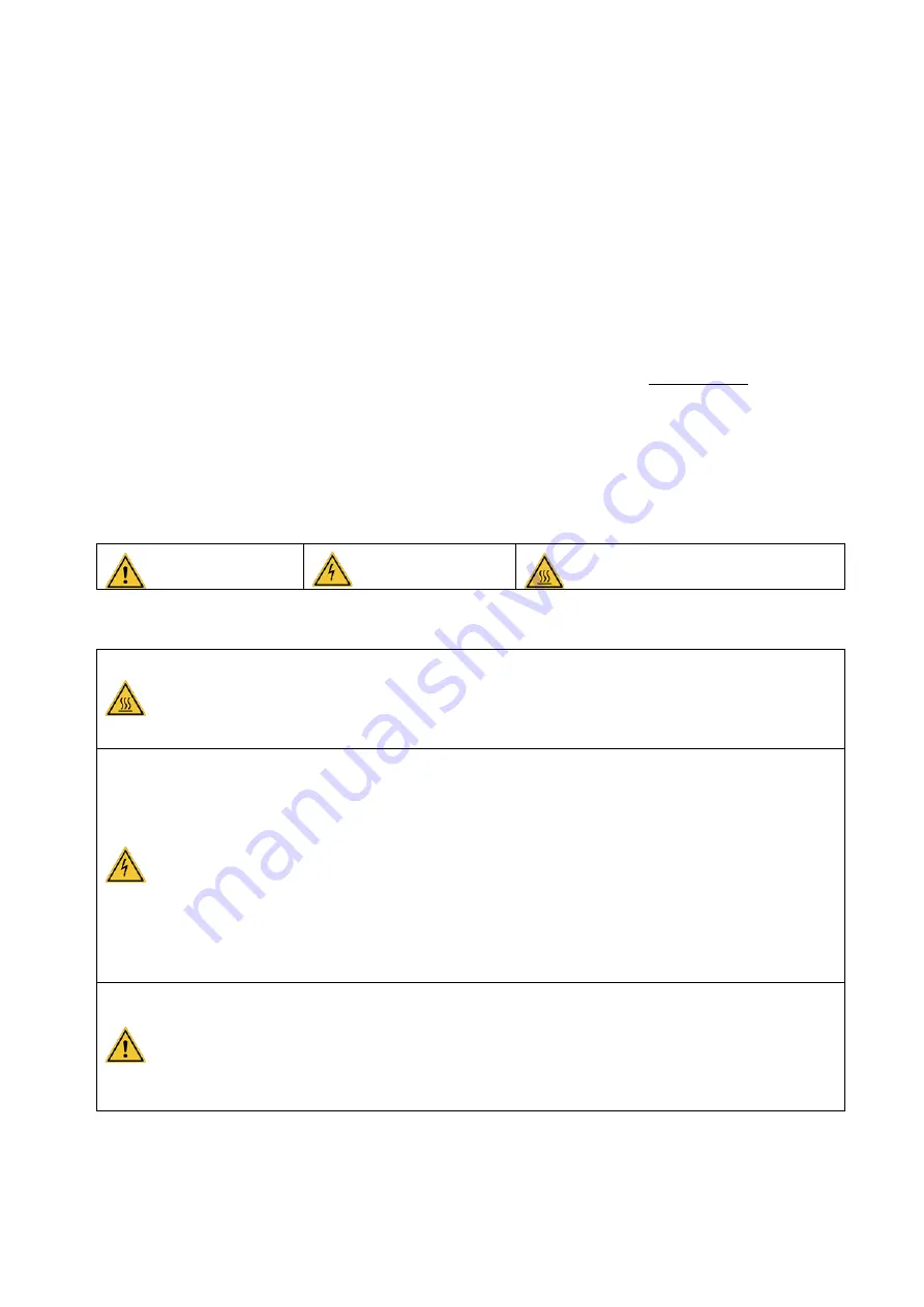
Pictograms’ meaning used in these instructio

ns for use: 


General warning


Electrical hazard


Burn hazard - Hot surface


Observe following safety instructions: 


-


During  operation  and  after  use, 

the  furnace  head  surface,  platform,  support,  tray  for 

sinterizing and cover may reach high temperatures: do not touch.


-


Wear  suitable  gloves  for  handling  prosthetic  objects,  tray  for  sinterizing  and  cover  and 
support. 


-


The unit has to be connected to an 

electrical installation in accordance

 with the applicable 

standard in the country in which it is being used. This installation has to provide 

protection 

against overcurrent, overload and ground faults.


-


This furnace requires its own power line and has to be connected to a circuit breaker. 

-


Connect it directly to the mains socket

. Do not use multiple sockets. 

-


Ensure that the 

connection cables

 are in perfect condition to prevent short circuits. 

-


Before  any 

technical  intervention

,  the  unit  has  to  be  switched  off  (with  the  breaker)  and 

disconnected from the main power supply. 

-


Do not spill liquid

 on the ventilation openings or inside the furnace. 


-


Ensure  that  the 

movement  of  the  tray  is  not  blocked  by  an  object

,  this  may  result  in 

malfunction of the unit and damage to certain components. 

-


The furnace must be placed on a 

flat surface

, keeping sufficient clearance around the unit to 

ensure proper ventilation 

(see chapter 4.2).


-


Do not block the ventilation openings

 to avoid overheating. 

Summary of Contents for e.ON sinter fast

Page 1: ...INSTRUCTIONS FOR USE Sintering furnace R v 011221...

Page 2: ...CTIONS 13 6 4 2 1 EXAMPLES OF CALCULATION 14 6 5 PARAMETER SETTING 14 6 6 PROGRAMS 15 6 6 1 PROGRAM PRE RECORDERED No 1 conventional cycle 15 6 6 2 PROGRAM PRE RECORDERED No 2 short cycle for up to 5...

Page 3: ...fast UGIN DENTAIRE 2 A EQUIPEMENT DESCRIPTION 3 6 7 N DESCRIPTION 1 Upper part of furnace 2 Platform 3 Support base and additional raise support 4 Touch screen 5 Power switch ON OFF rear side 6 Tray f...

Page 4: ...e furnace head surface platform support tray for sinterizing and cover may reach high temperatures do not touch Wear suitable gloves for handling prosthetic objects tray for sinterizing and cover and...

Page 5: ...the maximum number of trays to stack see chapter 6 7 damage equipment risk The chamber is made up refractory ceramic fibers Handle carefully They can release dust remove with a vacuum cleaner do not...

Page 6: ...must be disposed in accordance with applicable regulations in force 2 EC DECLARATION OF CONFORMITY The equipment s EC declaration of conformity is provided as appendix of instructions for use Content...

Page 7: ...Maximum temperature 1 730 C Operating temperature Less than 1 650 C Temperature accuracy 1 C Heating rate To 94 C minute maximum Screen High definition colour touch screen 7 155x87mm Number of progra...

Page 8: ...ts base never lift by upper part of furnace For transport the furnace must remain in an upright position not horizontal position Install the furnace in the packaging with the protective elements Also...

Page 9: ...rs and or other equipment that release heat Despite excellent insulation the furnace provides heat and in the long term can discolour surfaces that are nearest Do not shake the furnace avoid vibration...

Page 10: ...crew Remove carefully the cushioning foam pad protecting heating elements Then visually inspect the heating element no damage Avoid handling Install exhaust pipe a Install the conduit on the intended...

Page 11: ...y inspect the heating elements First time use press the arrow key upward and arrow key downward on touch screen Check the alignment of the platform with the base of the chamber movements must be made...

Page 12: ...ls Then press descent platform key ARROW KEY DOWNWARD an alert message appears in the status bar bottom of the screen Menu MENU or logo Microsoft Pull down menu appears as shown below Working interfac...

Page 13: ...is displayed on the screen For each program number the cycle parameters are displayed as a chart C represents temperature C and T represents time minutes Each program is two pages the first page disp...

Page 14: ...4 Final temperature of third stage and start temperature of fourth stage If necessary the parameters are programmed as for the previous steps Last time 121 Indicates the end of program temperature con...

Page 15: ...ature remains to 1490 C Time remains 10 minutes Time 03 10 minutes T03 10 minutes Zirconia SINTERING TEMPERATURES are given as indicative by disc manufacturer If necessary this one can be adjusted fro...

Page 16: ...1000 C Check with the cycle diagram that the furnace follows the requested temperature curve 6 6 1 PROGRAM PRE RECORDERED No 1 conventional cycle C01 50 0 C06 900 0 C11 0 0 C16 0 0 T01 50 T06 121 T11...

Page 17: ...T BE CARRIED OUT AS A PRECAUTIONARY MEASURE BEFORE THE FIRST USE OF THE FURNACE start the pre recorded program number 40 If use different types of zirconia zirconia of different brands or zirconia wit...

Page 18: ...dditional raise support on the platform during carry out a decontamination cycle ADVICE add in a tray with or without a cover white Zirconia smashed in multiple small pieces absorption of pollutants o...

Page 19: ...Clean with a vacuum cleaner if necessary see chapter 8 If the support is damaged or cracked do not use and replace it It is composed of a base and additional raise support Always position the two part...

Page 20: ...o trays Place the tray s at the center of support on the base and additional raise support Note if the zirconia beads are discoloration in yellow colour they must be replaced 6 7 2 2 TO PERFORM A SHOR...

Page 21: ...RUN the furnace starts to rise in temperature b the platform rises and stays closed 5 to 10 seconds c the platform goes down partially and holds about 5 min d the platform rises without closing comple...

Page 22: ...osition When the furnace is in standby or off the platform must be in the high position to avoid condensation Do not touch the display during a cycle to avoid manual interruption of the programme At t...

Page 23: ...without a cover white Zirconia smashed in multiple small pieces or powder Nacera Clean absorption of pollutants After running the program check the condition of the rods still whitish traces still con...

Page 24: ...s cleaner Cleaning wipes for optic products can also be used For avoid screen damage do not use a sharp object to operate the touchscreen Remove any pearl of small pieces stuck between the display and...

Page 25: ...of heating elements with a wrench supplied as an accessory Repeat for all the heating elements to replace 3 Unscrew the support elements of heating element with a wrench supplied as an accessory 4 Re...

Page 26: ...perature and time Adjust sintering temperatures if necessary see chapter 6 4 The furnace does not heat up It is necessary to test the continuity of the rods Do not use the furnace risk of material dam...

Page 27: ......

Reviews: