background image

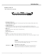
5

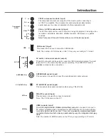
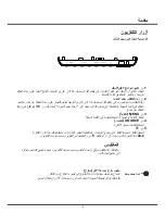
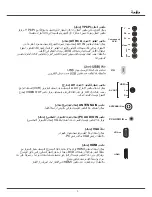
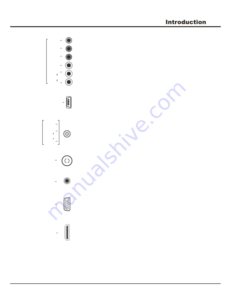
VGA

ANTENNA IN

ANTENNA IN socket (input) 

This socket can be used to connect the outside aerial or cable network.


AV audio + video mini sockets (output)

These AV out socket can be used to connect a VCR to record programs. You must 
leave the TV on the same channel you are recording. The VIDEO OUT socket 
p

 composite video connection.


rovides

VGA(PC) socket (input)

This socket can be used to connect a computer. 

Note: The VGA is same as the PC

 .

VIDEO

R

L

AV OUT

HDMI 

HDMI  sockets (input) 

The HDMI 

can be used to connect a 

PC with a compatible video card installed, certain DVD players or a high-definition 
compatible digital satellite decoder. This socket p

Note: 

The number of HDMI sockets on the TV may vary according to TV model. 

(High-Definition Multimedia Interface) socket 

rovides an uncompressed digital 

connection that carries both video and audio data by way of an integrated mini-plug 
cable.

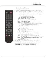
PC AUDIO IN socket (input)

This socket provides audio connection when using VGA (PC IN).

PC AUDIO IN

AUDIO

USB socket (input) 

USB 

This socket can be used to connect an USB device.

Note: 

The number of USB sockets on the TV may vary according to TV model. 


Y

Pb

Pr

YPbPr component sockets (input) 

The component sockets can recognize if the device you're connecting to
is Y Pb Pr compatible. The component sockets provide excellent picture
quality because the video is separated into three separate parts. 

Video

Component/

AV IN

L

R

Video + AV RCA audio sockets (input)

The AV IN sockets can be used to connect a range of equipment, including video 
recorders, camcorders, decoders, satellite receivers, DVD players, or games 
consoles.

Note: Component IN and AV IN share the same L/R Audio input jacks. 

Audio

Summary of Contents for UG55LED

Page 1: ...OPERATION MANUAL...

Page 2: ...nd Plug Power Cord and Signal Cable Use Environment Cleaning Hanging the TV Set on the Wall Buttons on the TV Sockets Remote Control Functions Switching off Menu Function Selecting a Signal Source CHA...

Page 3: ...Where the mains plug or an appliance coupler is used as disconnect device the disconnect device shall remain readily operable Where an all pole mains switch is used as the disconnect device the switch...

Page 4: ...ke the right left direction buttons on the remote and adjust menu controls Note In some menus VOLUME UP also acts like the OK button on the remote 1 PROGRAM UP DOWN button Scans up down through the ch...

Page 5: ...Multimedia Interface socket rovides an uncompressed digital connection that carries both video and audio data by way of an integrated mini plug cable PC AUDIO IN socket input This socket provides aud...

Page 6: ...Confirms your selection MUTE Reduces the TV s volume to its minimum level Press again to restore the volume USB Access the USB mode Menu Brings up the menu system VOL Increases or decreases the TV s...

Page 7: ...urned on directly or be in standby Note For some models s If the power indicator lights up the TV set is in standby mode Press the button on the remote control or on the TV set to turn on the TV witch...

Page 8: ...ifference between the light and dark areas of the picture Note Tint is available to be adjusted only when the system of the video signal is NTSC to display the selectable options then press to scroll...

Page 9: ...he available languages might differ depending on the model Aspect Ratio Press or OK to select the picture scale This options Include 4 3 16 9 Zoom1 Zoom2 Blue Screen Press or OK to turn On Off the Blu...

Page 10: ...ress DISPLAY to display the play console For the play console press to select an icon then press OK to confirm The play console includes Play Pause Prev Next Stop Repeat Mode Music Playlist Info Rotat...

Page 11: ...n when the system is reading or transmitting data avoid damaging the system or the device 3 Pay attention to the power supply of the device when you are using a mobile hard disk or a digital camera If...

Page 12: ...solution set by the PC Suggest to change to the best resolution or other standard resolutions of the Windows system Snowy dots and interference If the antenna is located in the fringe area of a televi...

Page 13: ......

Page 14: ...3 3 4 4 6 7 7 8 11 3 785 6281 7 0 237 21 6 5 1 USB 11 12 13 13 2...

Page 15: ...3 z z z z z z z z z z z z z z z z z z z z z z z z z...

Page 16: ...Earphone Out 1 2 OK 3 MENU 4 SOURCE 5 SOURCE MENU VOL PRO...

Page 17: ...AV RCA 9 1 9 YPbPr 3E 3U VIDEO R L AV OUT AV 9 9 5 9 2 287 VGA VGA 9 3 PC AUDIO IN PC AUDIO IN 9 ANTENNA IN ANTENNA IN 5 HDMI HDMI 0 9 0 Y Pb Pr Video Component AV IN L R...

Page 18: ......

Page 19: ...7 ANTENNA IN 9 8 z z...

Page 20: ...ning f e XWR 7XQLQJ 2 f 0 18 ATV Manual Tuning d c 79 0DQXDO 7XQLQJ 2 f XUUHQW KDQQHO f e 6HDUFK 2 f e Program Edit d c 2 f d c PICTURE PICTURE Picture Mode Color Temperature Noise Reduction Contrast...

Page 21: ...1 2 d c Sound Mode d c 6RXQG 0RGH 2 f d c 6WDQGDUG 0XVLF 0RYLH 6SRUWV 8VHU Treble f e 2 Bass f e 2 Balance f e 2 Auto Volume f e 2 XWR 9ROXPH 2Q TIME TIME Sleep Timer Auto Sleep OSD Timer Move Enter E...

Page 22: ...OSD Language Aspect Ratio f e 2 RRP RRP Blue Screen f e 2 OXH 6FUHHQ Key Lock f e 2 H RFN Region Language 2 2 0HGLD Encoding Standard f e 2 LQGRZV 62 0HGLD Reset f e 2 e HV USB Software Updated USB 86...

Page 23: ...86 6RXUFH d c 0HGLD 0HGLD 86 2 0HGLD f e 3 272 086 029 7 7 2 86 f e d c 2 86 86 86 3 272 2 86 f e d c 2 63 f e 2 2 7 086 2 86 f e d c 2 63 f e 2 2 7 029 2 86 f e d c 2 63 f e 2 2 LW 7 7 2 86 f e d c...

Page 24: ...12 3 3 03 03 03 03 7 7 86 86 8 6 03 86 86 03...

Page 25: ...13 VOL VGA...

Reviews: