background image

3

8

This unit is not to be installed in areas

subject to water-spouts.

9

Do not use water-jets to clean the unit.

10

This unit can work in a room temperature

range b5° and +50°C.

5 OPERATING PROCEDURES

1

Clean and sanitized the dispenser prior to

use following the instructions in chapter 7 CLEA-

NING AND SANITIZING PROCEDURES. 

2

Fill the bowl with the product, prepared

according to the instructions of the manufacturer. 

3

Install the cover above the container making

sure that it is placed correctly. 

4

Set the control switch (see charter 5.1. COM-

MAND DESCRIPTIONS)

5

The dispenser should always operate with

the cover installed in order to prevent possible

contamination of the product. 

6

The dispenser must run uninterruptedly; hea-

ting will stop automatically when the product is

ready for dispensing. The mixing device will con-

tinue to operate.

7

The dispenser is supplied with a container

with a closed removable bottom to facilitate clea-

ning and sterilisation.

5. 1 DESCRIPTION OF CONTROLS 

The dispenser is equipped with a general switch
whose functions are:

The dispenser is equipped with a thermostat, on

the right side, to adjust the temperature of the

product. 

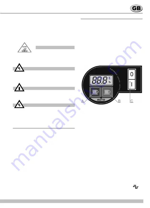
(ELECTRONIC VERSION)

The dispenser is equipped with a general switch
whose functions are:

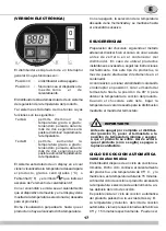
The dispenser is also equipped with an electronic
device, located on the right side, to control the
temperature of the product. This device has one
display, to show the set temperature and two keys
whose functions are the following:

On the display, the symbols °C or °F indicates the

current temperature unit and the symbol 

 in-

dicates the turning on of the heating element.

ATTENTION

Do not remove the container until the hot

plate is cold.

ATTENTION

Do not remove the container from the

dispenser when it contains hot products.

IMPORTANT

Place the unit on an horizontal surface.

ATTENTION

In case of damages, the power cord must

be replaced by qualified personnel only in

order to prevent any shock hazard. 

Position 0 :

power is turned off 

Position I :

mixer and heating device in wor-

king order 

Position 0

: power is turned off.

Position I

: mixing and hating on.

Key A

: to decrease the desired temperature

one degree by one; by keeping it

pressed for more than two seconds it

is possible to quickly decrease the

temperature.

Key B

: to increase the desired temperature

one degree by one; by keeping it

pressed for more than two seconds it

is possible to quickly increase the

temperature.

Summary of Contents for DELICE 5L UL

Page 1: ...OPERATOR S MANUAL CARNET D INSTRUCTIONS MANUAL DE INSTRUCCIONES Delice 5L UL...

Page 2: ...you want to make a fixed connection to the network connect the cord to a bipolar wall breaker with a contact gap of at least 3mm not use extension cords to connect the unit electrically 5 The dispense...

Page 3: ...the right side to adjust the temperature of the product ELECTRONIC VERSION The dispenser is equipped with a general switch whose functions are The dispenser is also equipped with an electronic device...

Page 4: ...cle The temperature and the length of the Automatic Cooking Cycle are factory preset To reset them turn the dispenser off and then turn it on keeping key A pressed On the display the Cooking Tem perat...

Page 5: ...4 ASSEMBLY 1 Put the drip tray and grill in place 2 Lubricate the faucet piston in the area A shown in fig 2 using food grade approved lubri cant figure 2 3 Reassemble the faucet assembly on the con...

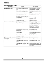
Page 6: ...rheated Thermal Protection tripped Check the voltage of the outlet Check the ventilation fins on the side panels obstructed or lower part of the distributor obstructed Check the viscosity of the produ...

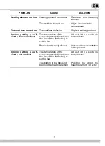
Page 7: ...rvice thermostat located on the side of the distributor is set too low Adjust it to a suitable temperature Product excessively diluted Increase the concentration of the product I m not getting a suffi...

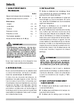
Page 8: ...omprenant la mise la terre conform ment aux normes en vigueur Si vous voulez r aliser un branchement fixe au r seau branchez le c ble un dispositif bipolaire de coupure fix au mur dont les ouvertures...

Page 9: ...nctionner couvercle ferm afin d viter une ventuelle con tamination du produit 6 Le distributeur doit fonctionner sans interrup tion Le chauffage s arr tera automatiquement lorsque le produit sera pr t...

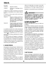
Page 10: ...est alors chauff jusqu 95 C et cette temp rature est maintenue pendant 15 minutes Une fois le cycle de cuisson automati que termin le produit est maintenu la tem p rature m moris e Les param tres de t...

Page 11: ...es qui sont en contact avec la boisson 3 Rincez toutes les pi ces lav es l eau cou rante 8 2 DESINFECTION La d sinfection doit tre effectu e avant de mettre en marche le distributeur Evitez que celui...

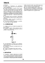
Page 12: ...ille les gouttes et la grille en place 2 Lubrifiez le piston robinet dans la zone A indiqu e sur la figure 2 uniquement avec la graisse usage alimentaire figure 2 3 R assemblez le robinet sur le conte...

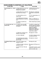
Page 13: ...ducteur ne tourne pas Le moteur est surchauff intervention du protecteur thermique Contr ler le voltage de la prise de courant Contr ler la ventilation ailettes des panneaux lat raux obstru es ou part...

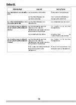
Page 14: ...dense Le thermostat de service plac sur le c t du distributeur est r gl sur une temp rature trop basse Le r gler la bonne temp rature Le produit est trop dilu Augmenter la concentration du produit Je...

Page 15: ...a en la placa Conectar el distribuidor en una red monofase ayud ndose de una toma a tierra en conformidad con las normas vigentes Si se quisiera realizar una conexi n fija a la red conectar el cable a...

Page 16: ...OS MANDOS 5 El distribuidor debe funcionar siempre con la tapa montada para evitar que el producto se contamine 6 El distribuidor debe funcionar ininterrumpidamente el calentamiento se parar autom tic...

Page 17: ...el termostato hasta la posici n de 90 C para obtener la temperatura de cocci n del producto Cuando el chocolate est listo bajar la temperatura al valor deseado para la distribuci n mediante el mando d...

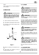
Page 18: ...r la tapa 2 Extraer el mezclador del eje central 3 Desmontar el grifo siguiendo la secuencia indicada v ase figura 1 figura 1 4 Levantar el contenedor para extraerlo 5 Extraer el caj n recogegotas y v...

Page 19: ...asivos 7 4 REMONTAJE 1 Montar el caj n recogegotas y la rejilla en sus alojamientos correspondientes 2 Lubricar el pist n del grifo en la zona A indicada en la Figura 2 utilizando exclusivamente la gr...

Page 20: ...do intervenci n del Protec tor t rmico Comprobar el voltaje de la toma de corriente Comprobar la ventilaci n aletas de los paneles laterales o parte inferior del distribuidor obstruidas Comprobar la v...

Page 21: ...o suficientemen te denso El termostato de servicio situado al lado del distribuidor est regulado a una temperatura demasiado baja Regularlo a la temperatura adecuada El producto est demasiado diluido...

Page 22: ...27 Golden heating plate holde Support dor plaque chauffante Soporte para plancha calentadora oro 3 10554 44000 M4 Clip Clip M4 Clip M4 4 22800 26415 Thermostat bulb holder Support boule du thermostat...

Page 23: ...ntenedor oro 22 22800 26414 Mixer M langeur Mezclador 23 22800 26412 Bowl shaft Arbre du r servoir Arbol del contenedor 24 22800 26419 Bowl shaft O ring OR de l arbre du r servoir OR para rbol central...

Page 24: ...95 C Term stato 5 95 C 6 Gear motor Motor ducteur Motoreductor ELECTRONIC VERSION 1 Switch Interrupteur Interruptor 2 Termic fuse 3 Gear motor Motor ducteur Motoreductor 4 Resistance Resistance Resis...

Page 25: ...25 NOTES NOTES NOTAS...

Page 26: ...26 DELICE UL NOTES NOTES NOTAS...

Page 27: ...27 NOTES NOTES NOTAS...

Page 28: ...02449 00029 R3 6 15E13 Ugolini spa Via dei Pioppi 33 20090 Opera MI Tel 02 5300591 www ugolinispa com...

Reviews: