12
MINIGEL
1 TECHNICAL CHARACTERISTICS
We reserve the right to amend this manual without notice.
2 INTRODUCTION
Read this instruction booklet carefully in order to familiarise
yourself with all aspects of the dispenser.
Like all mechanical products, this machine will require cleaning
and maintenance. Good operation can also be affected by any
errors made by the operator during disassembly and cleaning.
For this reason, in the case of daily operations such as
disassembly, cleaning, sanitising and reassembly, it is important
that the person using the dispenser is aware of the procedures
and can perform them without making errors.
3 INSTALLATION
1
Remove the dispenser from the packaging, which you
should keep in case it is needed in the future.
2
Check that the dispenser has not been damaged during
transport. If it has, make a report to the carrier immediately.
3
Position the dispenser on a bench capable of supporting the
weight, even at full load,
bearing in mind the IMPORTANT
warning in point 1 above.
4
Allow a minimum clearance of at least 15 cm all around the
dispenser so as not to impede the flow of cooling air.
5
Check the stability of the device, adjusting the height of the
feet if necessary. In the event that the dispenser is provided
with a series of high feet (approximately 100 mm), these must
replace the original ones.
6
Before plugging in the dispenser, check that the mains
voltage is the same as that indicated on the data plate. Connect
the dispenser to a single phase network, using an outlet
complete with earthing as defined by current standards. If the
dispenser has no plug, connect one to the cable that complies
with applicable regulations in the country of use, equipped with
earth contacts or a jack and suitable for currents of at least 10
A 250 V (for areas with voltages of 220-230 V 50-60 Hz) and 20
A 250 V (for areas with voltages of 100-115 V 50-60 Hz). If you
prefer to create a fixed connection to the mains, connect the
cable to a bipolar wall switch with contact opening of at least 3
mm. Do not use extension cables to connect the device to the
mains.
7
The dispenser does not leave the factory pre-washed and
sanitised. Before use, it must be disassembled, washed and
sanitised, following the instructions in Chapter 5.3 CLEANING.
4 TO OPERATE SAFELY
1
Do not
use the dispenser without reading this instruction
booklet first.
2
Do not
use the dispenser if it is not properly earthed.
3
Do not
use extension cables to connect the dispenser to
the mains.
4
Do not
operate the dispenser if the panels are not in place
and secured with screws.
5
Do not
impede the flow of cooling air. Allow a minimum
clearance of at least 15 cm (6”) all around the dispenser.
6
Do not
put fingers or objects into the slots in the panels and
in the opening of the tap.
7
Do not
disassemble the tank or remove the mixers or
panels for cleaning or maintenance without ensuring that the
dispenser is unplugged.
Transparent removable bowls
n
1
2
3
Capacity of each bowl, approx.
l
6
6
6
Dimensions:
width
cm
20
39
59
depth
cm
48
48
48
height
cm
62
62
62
Net weight, approx.
kg
25
45
61
Gross weight, approx.
kg
27
48
64
Hermetic compressor
Air-cooled condenser
Overload protector
Noise level lower than 70 dB (A)
IMPORTANT
Electrical characteristics: read the data on the plate of
each individual dispenser. This is located at the bottom
of the front panel, behind the drip tray on the right. The
serial numbers of the devices (preceded by the symbol #)
are shown on the frame below the rear panel. Always
refer to the data shown on the plate.
IMPORTANT
When transporting or lifting the dispenser, never pick it
up by the transparent containers or the evaporator cylin-
ders. The manufacturer is not liable for damage caused
by such mishandling.
ATTENTION
Make sure the device is properly earthed, otherwise you
may cause electric shocks to persons or damage to the
dispenser.
IMPORTANT
Place the device in such a way that the power cable is
easily accessible.
IMPORTANT
This device is not meant to be used by children or per-
sons with mental or sensory impairment, or with lack of
sufficient knowledge or experience unless supervision or
instruction is provided concerning the use of the device
by a person responsible for their safety.
Children should be supervised to ensure they do not play
with the device.
MINIGEL 1
MINIGE
L 2
MIN
IGEL 3
Summary of Contents for minigel
Page 1: ...MANUALE D ISTRUZIONI OPERATOR S MANUAL MiniGEL...
Page 19: ...19...
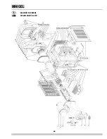
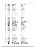
Page 20: ...20 MINIGEL ELENCO RICAMBI SPARE PARTS LIST...
Page 22: ...22 MINIGEL NOTE NOTES...
Page 23: ...23 NOTE NOTES...


