Internal error
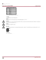
The dosing pump carries out a self-check, which switches off the pump if no stroke has been carried out two seconds after motor start-up (e.g. if back pressure is too high) or if the
proximity switch (stroke sensor) does not respond (display E-2). The alarm is reset by pulling out the mains plug.
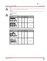
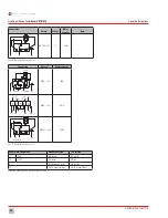
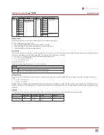
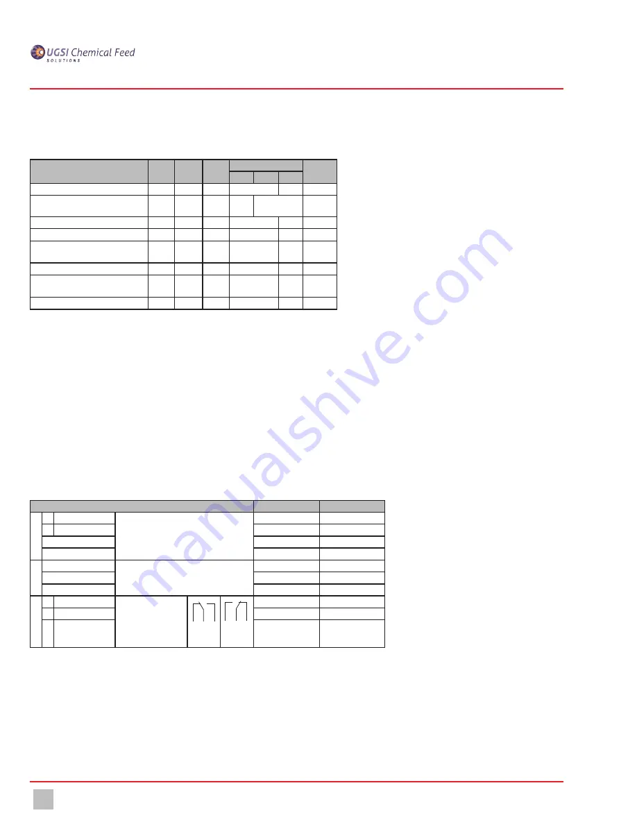
The functions of the LEDs and built-in warning alarm relay are shown in the following table:
Condition
LED 1
ON
LED 2
Extern
LED
Alarm
Warning alarm relay Display
R0
RW
R1
Power supply absent
closed
-
Dosing pump running
closed
Number
of strokes
Dosing pump off (by ON/OFF switch)
closed
OFF
Dosing pump off (by external contact)
closed
OFF
Level pre-alarm
*)
flashes closed
Number
of strokes
Level main alarm
*)
closed
E - L
Dosing pump fault (proximity switch,
stroke sensor)
*)
closed
E - 2
Dosing pump fault (current < 4 mA)
closed
E - I
*) LED 2 is lit in operating modes 1.1 - 1.64; 0...20 mA and 4... 20 mA
8.6 Other settings
8.6.1 Max. number of strokes
Press and hold the "Mode" and "I/O" keys while applying the voltage, and set the maximum pump stroke frequency using keys
▼
and
▲
. When the "Mode" key is released, normal
operation starts.
8.6.2 Warning alarm relay connection
Relay not activated in case of fault or OFF: When voltage is applied, press and hold "Mode" and
▲
keys. Display: "RE0". Relay activated in case of fault or OFF: When voltage is
applied, press and hold "Mode" and
▼
keys. Display: "RE1".
8.7 Factory setting
•
The initial status of Encore
®
MB is "OFF".
•
Depending on the technical specifications, the maximum stroke frequency is preset (see section 5).
•
In case of a fault or "OFF", the warning alarm relay is not activated.
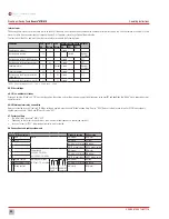
8.8 Connections and cable assignments
Encore
®
MB control unit
Standard version CSA version
l
L1 RUN
Motor
BR (brown)
BK (black)
L2 STOP
BK (black)
RD (red)
N
BU (blue) or GY (grey) WH (white)
PE
GN/YE (green/yellow) GN/YE (green/yellow)
k
L
Power supply
230 V AC, 50/60 Hz
or 120 V AC, 50/60 Hz
BR (brown)
BK (black)
N
BU (blue) or GY (grey) WH (white)
PE
GN/YE (green/yellow) GN/YE (green/yellow)
m
R0 Break contact
Warning alarm relay
(4.9 foot (1.5 m) cable)
R0 RW R1
Fault
R0 RW R1
Operation
BR (brown)
RD (red)
Rw Changeover contact
BU (blue) or GY (grey) WH (white)
R1 Make contact
BK (black)
BK (black)
28
Diaphragm Dosing Pump
Encore
®
MB/ME
Operating Instructions
CF.450.410.001.IM.1114
Summary of Contents for Encore MB
Page 3: ...3 Diaphragm Dosing Pump Encore MB ME Operating Instructions CF 450 410 001 IM 1114 ...
Page 48: ...48 Diaphragm Dosing Pump Encore MB ME Operating Instructions CF 450 410 001 IM 1114 ...
Page 50: ...19 Notes 50 Diaphragm Dosing Pump Encore MB ME Operating Instructions CF 450 410 001 IM 1114 ...
Page 51: ...51 Diaphragm Dosing Pump Encore MB ME Operating Instructions CF 450 410 001 IM 1114 ...
Page 52: ...Encore MB ME Diaphragm Dosing Pump MANUAL NO CF 450 410 001 IM 1114 CF 450 420 001 IM 1114 ...

