background image


Umwelt-Geräte-Technik GmbH

  |  Eberswalder Str. 58  |  D-15374 Müncheberg  |  phone: +49 (0) 33 43 2 - 89 575 |  

www.ugt-online.de

       Page 18 of 29 


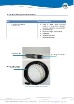
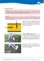
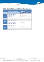
Step 3: Connect the data (power) cable 


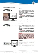
UGT Logger: 
 

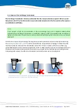
Connect the UGT power and data transfer cable via 
a ventilated 4-pole connector to a UGT data logger 
(example UGTlogger DL-2000). 
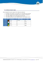
The Pin assignment can be found in the 

calibration 

certificate. 

All 

bus  addresses

  are  addressed  during  the  setup 

process by UGT and can be found in the 

calibration 

certificate

Download the UGT-LOG software to your PC. 
Follow  the  provided  logger  and  software 
instruction. 
As a service, UGT GmbH can pre-install your project 
on a UGT logger. 


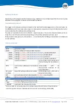
External Logger: 
 

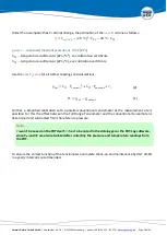
Connect the UGT power and data transfer cable via 
a  ventilated  4-pole  connector  to  an  external  data 
logger. 
The Pin assignment can be found in the 

calibration 

certificate. 

All 

bus  addresses

  are  addressed  during  the  setup 

process by UGT and can be found in the 

calibration 

certificate.


Caution! 

In order to change or view bus addresses of the 
FRT we advise to use FRT log. Experienced users 
might  want  to  use  dataloggers  or  terminal 
programs  for  serial  ports  following  the 
instructions in chapter 5.  


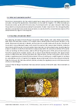
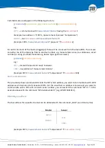
PC interface: 

 
Use FRT LOG to display the FRT values graphically 
and change 

bus addresses

 
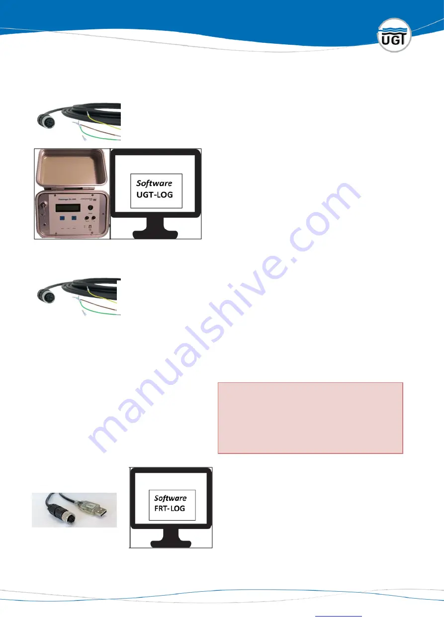
Connect the UGT power and data transfer cable via 
a  USB  2.0  converter,  a  plug  to  RS-485  to  your 
computer. 
Install the software UGT FRT-LOG. 
Follow the provided software instruction.


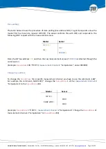
   External Logger 
Summary of Contents for 108015

Page 1: ...g Manual Full Range Tensiometer Version 20 07 20 Umwelt Ger te Technik GmbH Eberswalder Str 58 D 15374 M ncheberg phone 49 0 33 43 2 89 575 fax 49 0 33 43 2 89 573 e Mail info ugt online de www ugt on...

Page 2: ...Does a Tensiometer Work 8 2 4 Product versions 10 2 5 Technical data 10 3 Structure and basic functions 11 3 1 structure 11 3 2 How to Operate the Full Range Tensiometer 12 4 Installation of the Full...

Page 3: ...indirectly as a derived variable but via a direct pressure measurement Even after drying out beyond the limits of the measuring range the measurement is continued independently as soon as the moistur...

Page 4: ...problems with your product please contact Email support ugt online de We look forward to your inquiries or questions and are with pleasure at your disposal Phone 49 0 33432 89 575 Fax 49 0 33432 89 57...

Page 5: ...High pressure may lead to permanent damage of the pressure transducer Avoid installing the tensiometer with high pressure surges Protect from high pressure CAUTION Sudden pressure drops inside the ten...

Page 6: ...tional equipment Full Range Tensiometer Protective case Cable for power supply and data transfer inclusive M12 connector standard length 5 m customizable Installation auger Standpipe length customizab...

Page 7: ...ntial or simply pressure head The tension is defined as a negative pressure and therefore is signed positive if the applied pressure is negative A pressure of 50 kPa in the pore water accords a tensio...

Page 8: ...a porous cup usually made out of ceramic The pores of the ceramic cup are filled with water and connect the liquid of the measurement chamber inside the tensiometer with the water in the soil outside...

Page 9: ...oint of the ceramic This point is reached when the negative pressure is high enough to suck air through the biggest pore of the ceramic The upper limit of the measurement range of a tensiometer is def...

Page 10: ...ement range tension 100 1500 kPa pF 4 2 2 5 Technical data Technical Parameters Measurement range Tension 100 500 kPa FRT 5D 100 1500 kPa FRT 15D Operating temperature 1 39 C surrounding soil temperat...

Page 11: ...8 D 15374 M ncheberg phone 49 0 33 43 2 89 575 www ugt online de Page 11 of 29 3 Structure and basic functions 3 1 structure Ceramic cup Stainless steel shaft Plastic case optional with thread for sta...

Page 12: ...n equation 1 by using the measured temperature is done via the following equation 1 2 2 0 Tension kPa pref Reference pressure temperature compensated kPa pcurrent Measurement value pressure kPa Transf...

Page 13: ...distilled water for at least 24 hours Keep the ceramic cup wet during transportation by using the protective case until installation Storage If the tensiometers are not installed store them in a dry s...

Page 14: ...the tensiometer to the data logger PC The cable can also be installed underground It is recommended to lay the cable in such a way that it is protected from animals Choose a cable according to the re...

Page 15: ...iometer can be installed horizontally or vertically In both cases make sure the whole plastic case including plug is buried to prevent temperature conduction via the case which may influence the measu...

Page 16: ...the standpipe onto the thread on the upper end of the plastic case The standpipe remains in the soil with the tensiometer Horizontally installation Dig up the soil up to the designated measurement dep...

Page 17: ...alibration certificate Full Range Tensiometers are connected via a ventilated 4 pol connector The power supply of the connected sensor is carried out via two pins The supply voltage must be in the ran...

Page 18: ...ject on a UGT logger External Logger Connect the UGT power and data transfer cable via a ventilated 4 pole connector to an external data logger The Pin assignment can be found in the calibration certi...
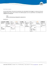
Page 19: ...emperature and 3 pressure which are the channels of main interest for the user In order to be able to use more than one FRT example FRT 1 and FRT 2 and FRT 3 each measurement channel has to be given a...

Page 20: ...signment unchangeable bus address preset but changeable EXAMPLE see calibration certificate or FRT Log FRT 1 1 service calibration 2 temperature 1 temperature 3 pressure 2 pressure 4 service calibrati...

Page 21: ...ess Table of commands Command GSN get serial number GADx get bus address of measurement channel x GAD1 reading bus address of measurement channel 1 service calibration GAD2 reading bus address of meas...

Page 22: ...ddresses serial number or string multiple characters eg Device type generic answer ANSWER RETURNCHARACTER e g OK r received request and ready to answer 100 r bus address of measurement channel Example...

Page 23: ...009000 r Here the OP bus address 100 and then the raw measurement value of 009000 is collected through the command GN Example bus address 100 FRT 3 measurement channel 2 temperature value 009000 Chang...

Page 24: ...l of the device program you are using Below is an example code snippet for the dataTaker Code 1SERIAL OP3 013 w 100 e GN 013 d 99CV Explanation command 1SERIAL OP3 013 w 100 e GN 013 d 99CV general Da...

Page 25: ...s limited to 40 C to 60 C However the digital version of the Full Range Tensiometer is able to display temperature values between 327 68 C and 327 67 C with a step size of 0 01 C The temperature value...

Page 26: ...Pcurrent current measured pressure value 16384 31 calibration constants Note that the measurement range of the pressure sensor limits the measurement range of the Full Range Tensiometer Note The conv...

Page 27: ...eramic with distilled water Then saturate the ceramic in distilled water Repeat this procedure several times to thoroughly flush the ceramic and the polymer Caution The case of the tensiometer must no...

Page 28: ...ter at least for 3 hours in water with a free surface e g water filled beaker and a constant temperature of 20 C Note that the ceramic is not allowed to touch the bottom of the water tank and that the...

Page 29: ...rther readings and calculations 1 2 2 0 Further a simplified calibration with a parallel conventional tensiometer at the measurement site is possible For this the offset between the Full Range Tensiom...

Reviews: