Umwelt-Geräte-Technik GmbH | Eberswalder Str. 58 | D-15374 Müncheberg | Tel.: +49 (0) 33 43 2 - 89 575 |
6.7
Soil Tensiometer
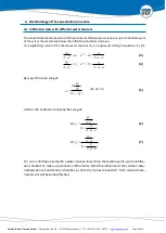
During infiltration tests the water movement is influenced by gravitation and matrix poten-
tial. Reaching steady-state flow conditions the influence of the matrix potential is widely
subsided, given that the infiltration front is moving deep in the soil. The infiltration is almost
solely influenced by gravitation.
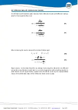
But the unit gradient of 1 cmWS/cm only develops at a uniform distribution of the ku-func-
tion over the infiltration range. For layered soils the flow velocity is determined by the layer
with the least hydraulic conductivity and the resulting surcharge. Since the flow rate is con-
stant over the soil depth (“series connection”) in each case the gradient forms according to
the k-value of the soil layers.
For layers near to the surface the effective gradient can be determined, if the effective
tension is measured prior to the lower layer boundary. Herefore up to three soil tensiom-
eters can additionally be installed at a shallow depth. The soil tensiometers as well as the
appropriate outer ring are available at UGT-GmbH.
7.
Infiltration Measurement with the tension infiltrometer
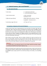
To determine a representative ku-function a hood Infiltrometer test from tension “zero”(kf-
value) and the bubble point of the soil is advisable. Thereby the efficient macropores are not
distorted or clogged.
From the bubble point the measurement needs to be made with the tension infiltrometer.
The fine sand of the contact layer needs to be chosen in such a way that its hydraulic conduc-
tivity is always higher than the hydraulic conductivity of the tested soil.
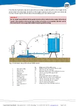
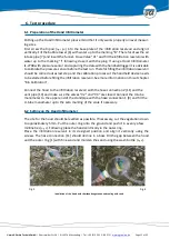
For installation connect the tension chamber to the infiltration vessel and the U-tube manom-
eter using connecting hoses [11] and [9]. Make sure that valve "V2" is shut. The vent pipe [10]
is not used for the tension infiltrometer.
The designed measurement site needs to be smoothened. Following place the outer ring at
the measurement area and fill it with fine sand up to 2 mm. Cover the measuring area inside
the ring with fine dry sand about 2mm high. Thereafter cover the fine sand filled measurement
area with a waterproof foil and place the tension chamber even on the foil. Choose the im-
mersion depth “T” of the air intake pipe slightly bigger than the chamber height “Hk”. Fill the
tension chamber opening the valve “V1” and suck off air through the hose connection [9] until
the water level in the standpipe reaches center scale.
To start the infiltration flow, lift the chamber and remove the foil. Putting the chamber back
onto the measurement area, turn it slightly to establish a good contact with the fine sand.
Subsequently the measurement proceeds in the same way as the measurement with the
hood did. As soon as the aeration at the Mariotte water supply starts, the effective water
tension set by the immersion depth “T” according to equation (11) takes effect at the soil

