Umwelt-Geräte-Technik GmbH | Eberswalder Str. 58 | D-15374 Müncheberg | Tel.: +49 (0) 33 43 2 - 89 575 |
5.
Technical Parameters, Set Up and Operation
5.1
Technical Specifications
Tension area:
0 … bubble point with hood
0 … 60 hPa with tension chamber
Tension measurement:
U-tube manometer
Resolution 0.1 hPa
Infiltration measurement:
Differential pressure sensor 0 - 70 mbar
Resolution 1 mm water column
Conductivity range of the soil
10
-3
m/s to 10
-7
m/s
5.2
Assembly and operation of the Hood Infiltrometer
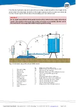
A hood [2] with circular base is standing directly on the soil surface. The space under the hood
is filled with water, hydraulic pressure head getting controlled through a MARIOTTE water
supply system [5, 6, 7]. Water-saturated fine sand is used to seal the edge of the hood against
the soil up to an outer ring [1]. Such sealing will be effective only if the pressure in the water
volume under the hood is negative. The negative pressure can be adjusted freely from zero
up to the bubble point (air permeation point). The soil pore system on the measuring surface
will remain absolutely undisturbed.
When setting up the test system, first the overflow chamber [3] under the hood has to be
filled – well controlled - with water. Upon overflow of that chamber begins the volume under
the hood gets filled with water and the infiltration into the soil starts. The enclosed air is piped
into the air volume of the infiltration reservoir [5] through the vent pipe [10].
Attention!
For unstable soils or non-structured sands the soil surface under the overflow chamber
should be prevented from flushing out applying a rag.
After the air escape hose has been closed [V2, V3], the water volume under the hood remains
in steady-state. Now the infiltration flow is delivered directly from the infiltration reservoir of
the MARIOTTE water supply system from where the reading can be taken of a scale (filling
height).

