Umwelt-Geräte-Technik GmbH | Eberswalder Str. 58 | D-15374 Müncheberg | Tel.: +49 (0) 33 43 2 - 89 575 |
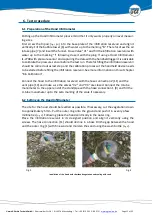
6.5
Measuring the infiltration rate
After choosing the water tension the leakage rate “
Z/
t“(cm/s) is measured on the infil-
tration reservoir. Therefor the filling height Z is recorded as a function of time (if possible,
Z > 1cm).
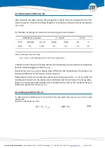
For the data recording it is convenient to use a log as shown in table 1.
1) Us = Us(le) + Us(ri) (left/right limb of the U-tube manometer)
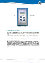
In addition to the manual recording the data for the leakage rate can also be recorded dig-
ital with the Micrologger IL-2700 (
Chapter 8
).
Each test has to be run up to a steady-state infiltration rate. Depending on the type of soil
involved, infiltration to mid-column will be required.
Following each test run increase the water tension step by step (
h 1 - 2 cm) up to the soil
bubble point. Determine the steady-state infiltration rate for each step. This being calcu-
lated from the steady-state leakage rate A divided by the ratio of the sectional areas of
infiltration reservoir to hood (
chapter 7
).
6.6
Bubble point (BP) of the soil
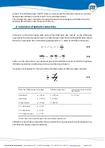
To determine the bubble point of the soil Shut [V1] and watch the pressure rise on the U-tube
manometer.
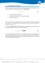
Determine the maximum of Us.
max
S
S
U
H
BP
( BP < 0 )
(14)
Infiltrations reservoir
U – Tube
1)
Hood
Time
Z (Scala)
Z /
t
Us(le)
Us(ri)
Hs
h
min:s
cm
cm/s
cm
cm
cm
cm
Table 1: Heading for data recording

