Umwelt-Geräte-Technik GmbH | Eberswalder Str. 58 | D-15374 Müncheberg | Tel.: +49 (0) 33 43 2 - 89 575 |
surface. The infiltration rate “
Z/
t“(cm/s) is measured at the infiltration reservoir until the
steady-state infiltration rate for tension h1 can be determined.
Then change the water tension by changing the depth of submergence and determine the
steady-stat
e
infiltration rate for water tension h
2
.
8.
Calculation of hydraulic conductivity
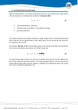
In the test run the final steady-state value of the infiltration rate “
Z/
t” on the infiltration
reservoir at the chosen water tension h is determined. Insert the according infiltration rate of
the soil v
B
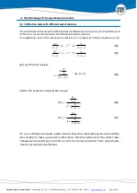
in equation (12). The following applies (with rs = radius of infiltration reservoir).
t
Z
r
a
Q
S
B
2
2
(15)
t
Z
q
t
Z
a
r
a
Q
S
B
2
2
2
(16)
Factor q is the ratio of the cross-sectional area of the infiltration reservoir and the respective
infiltration areas that are effective on the soil surface (see Table 1).
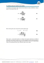
In equation (10) applies for the ratio of the infiltration rates at different water tensions:
t
Z
t
Z
Q
Q
2
1
2
1
(17)
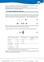
Radii of the infiltration areas (outer rings)
Infiltration areas on soil
Cross-sectional area of infiltra-
tion reservoir
Hood (small)
a
1
= 8.8 cm
F
1
= 240 cm²
F
i
= 75.1 cm²
Hood (large)
a
2
= 12.4 cm
F
2
= 483 cm²
Tension chamber
a = 12.4 cm
F = 483 cm²
F
i
/ F
1
(small hood)
q
1
= 0.,313
F
i
/ F
2
(large hood)
q
2
= 0.156
F
i
/ F
(Tension chamber)
q = 0.156
Table 2: Technical details of apparatus and calculation parameters
Infiltration area at Table 2 describes the area within the ring, because the sand between ring
and hood has usually a high conductivity.


