background image


Umwelt-Geräte-Technik GmbH  |  Eberswalder Str. 58  |  D-15374 Müncheberg  |  Tel.: +49 (0) 33 43 2 - 89 575 |  

www.ugt-online.de

          Page 20 of 32 

9.6


Calibration 


The calibration menu can be found in the menu “Options” as well as in the sub menu for 
choosing the memory space for a tension. This enabling to easily access the calibration 
menu before each measurement if needed.  
Offset-value and scaling factor can be calibrated separately. Both values need to be set to 
execute a measurement. 
The offset is usually calibrated at a pressure of 100 mmWC. Therefore fill the infiltration 
reservoir up to 100 mm at the scale and press the “Start”-button. But it is also possible to 
calibrate the offset at any other pressure. If the offset calibration doesn`t accord with the 
scale the absolute values recorded by the handheld device don`t match with the scale, but 
it has no effect on the differences. 
 
The  scaling  factor  is  usually  calibrated  at  a  pressure  of  600  respectively  610  mmWC. 
Therefore the infiltration reservoir is filled up to 600 mm (respectively610 mm) and the 
current  pressure  is  entered  into  the  handheld  device  and  confirmed  with  the  “Start”-
button.  It  is  possible  to  use  any  other  pressure  value  for  this  calibration  too,  but  for 
accuracy reasons it is recommended to use the highest possible pressure difference. The 
plug is supposed to stay open for the calibration 
 
For  a  convenient  execution  it  is  useful  to  calibrate  the  offset  after  putting  up the  Hood 
Infiltrometer at the test site but before filling the infiltration reservoir and to calibrate the 
scaling factor directly after filling the infiltration reservoir (still open against atmosphere). 


9.7


Configuring the measurement interval /Starting a measurement 


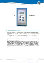
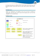
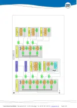
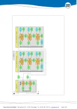
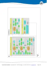
The  measurement  interval  is  defined  before  every  measurement.  To  get  to  this  point 
proceed as shown in the scheme on page 18 to 22. First of all the handheld device IL-2700 
is switched on pushing the “On”-button. The measurement site is chosen by pushing the 
“Step”-button  accordant  times  and  confirming  it  pushing  the  “Start”-button.  Thus 
reaching the menu for managing the measurement sites. Measurement sites already taken 
by data are marked with OK and can be deleted in this menu if needed. If the measurement 
site is still clear the tension menu is reached by pushing the “Start”-button.the designated 
tension is chosen using the “Step”-button. Generally tension 1 for the first set up tension 
of the measurement continuing for every following tension. Confirmation of the tension 
with the “Start”-button leads to the menu for managing the tensions. If needed already 
set up tensions can be deleted or a calibration can be done in this menu if this hasn`t been 
done before at the options menu. 
Push the “Start”-button right at the first menu item (Start) to start the measurement. 
 

The  display  shows  „Samples:  H0M00S00”  to  set  first  of  all  the  hours  (H),  following  the 
minutes (M) and last the seconds (S) of the  measurement interval. The numerics can be 
raised by one pushing “Step”. Holding the “Step”-button causes automatic steps by ten for 
minutes and seconds until the button is let go. “Start” confirmes the entry and switches to 
the next smaller timescale. The changing of the lower time scale doesn`t affect the higher 
time scale. (The set minutes don`t change if the seconds change from 60 to 0). In case of a 
wrong entry it is possible to go back for correction pushing “On”. After entering the seconds 

Summary of Contents for IL-2700

Page 1: ...Manual Hood Infiltrometer IL 2700...

Page 2: ...Preparation of the Hood Infiltrometer 12 6 2 Setting up the Hood Infiltrometer 12 6 3 Filling the hood 13 6 4 Choosing the effective water tension 13 6 5 Measuring the infiltration rate 14 6 6 Bubble...

Page 3: ...ction free manner The effective increase in pressure on the soil surface can be freely selected between zero and a vacuum up to the bubble point of the soil There are several ways to contact UGT if yo...

Page 4: ...le for manual level recording 1 and pressure sensor for electronic level recording Handheld instrument IL 2700 1 Read out software IL 2700 1 U tube manometer with field tripod 1 Infiltration hoods 2 R...

Page 5: ...c conductivity L T ku Hydraulic conductivity L T LDP Bubblepoint L Q Steady state flow V T q Ratio of two source areas rs Effective radius of the infiltration area L T Submersion depth of the air inta...

Page 6: ...a negative pressure up to the bubble point air permeation value of the soil That pressure head is measured precisely by means of a supplemental U tube manome ter An additional soil tensiometer measure...

Page 7: ...solution for a large number of two and three dimensional flow processes It is the regular basis for the interpretation of test results with the infiltrome ter systems common so far According to WOODIN...

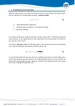
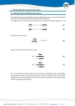
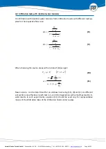
Page 8: ...r neighboring values of the chosen water tensions h1 h2 applies according to equations 1 2 4 1 1 2 1 a e k a Q h f 3 4 1 2 2 2 a e k a Q h f 4 By way of division we get ln 2 1 2 1 h h Q Q h1 h2 0 5 An...

Page 9: ...low rate When choosing the source areas with a ration of 10 we get 1 2 F q F 2 a F 10 1 1 4 2 1 1 2 1 Q Q q a Q Q q 11 Now ku and can be determined for an unknown soil using 11 8 and 1 As different so...

Page 10: ...effective only if the pressure in the water volume under the hood is negative The negative pressure can be adjusted freely from zero up to the bubble point air permeation point The soil pore system o...

Page 11: ...needs to be supported additionally ring with bearing Fig 2 Schematic setup of the Hood Infiltrometer 1 Fine sand sealing 2 Plastic hood 3 Buffer vessel 4 Standpipe 5 Infiltration reservoir 6 Bubble To...

Page 12: ...cess at the handheld device needs to be started before filling the infiltration reservoir See more information on this at chapter 8 6 Calibration Connect the hood to the infiltration reservoir with th...

Page 13: ...eep it closed Slowly open the aeration valve V2 Thereby the space under the hood is set to a negative pressure and the water flows over the overflow chamber Now the filling of the hood started Shut V2...

Page 14: ...IL 2700 Chapter 8 Each test has to be run up to a steady state infiltration rate Depending on the type of soil involved infiltration to mid column will be required Following each test run increase the...

Page 15: ...ereby the efficient macropores are not distorted or clogged From the bubble point the measurement needs to be made with the tension infiltrometer The fine sand of the contact layer needs to be chosen...

Page 16: ...es with rs radius of infiltration reservoir t Z r a Q S B 2 2 15 t Z q t Z a r a Q S B 2 2 2 16 Factor q is the ratio of the cross sectional area of the infiltration reservoir and the respective infil...

Page 17: ...hnical Data The UGT micrologger IL 2700 has two interfaces Input IN for the sensor data cable socket at the left side and Output RS 232 for the PC data cable socket at the right side see Fig 5 Sensor...

Page 18: ...sed in terms of Escape Hence the Start button always leads to the next lower menu section and the On buttonback to the next higher menu section The operation of the Step button relates to the down arr...

Page 19: ...al and afterwards the tension is set up Subsequently the measurement itself begins For each measurement a maximum of 100 values can be recorded But after reaching a steady flow rate only the preset nu...

Page 20: ...ation reservoir still open against atmosphere 9 7 Configuring the measurement interval Starting a measurement The measurement interval is defined before every measurement To get to this point proceed...

Page 21: ...with the Start button Now the set tension can be entered using the Step button Here the Start button starts the actual measure ment 9 8 Options menu Besides the configuration and calibration menu als...

Page 22: ...Umwelt Ger te Technik GmbH Eberswalder Str 58 D 15374 M ncheberg Tel 49 0 33 43 2 89 575 www ugt online de Page 22 of 32...

Page 23: ...Umwelt Ger te Technik GmbH Eberswalder Str 58 D 15374 M ncheberg Tel 49 0 33 43 2 89 575 www ugt online de Page 23 of 32...

Page 24: ...Umwelt Ger te Technik GmbH Eberswalder Str 58 D 15374 M ncheberg Tel 49 0 33 43 2 89 575 www ugt online de Page 24 of 32...

Page 25: ...Umwelt Ger te Technik GmbH Eberswalder Str 58 D 15374 M ncheberg Tel 49 0 33 43 2 89 575 www ugt online de Page 25 of 32...

Page 26: ...Umwelt Ger te Technik GmbH Eberswalder Str 58 D 15374 M ncheberg Tel 49 0 33 43 2 89 575 www ugt online de Page 26 of 32...

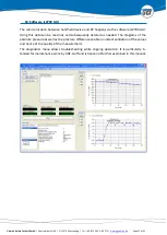
Page 27: ...IL2700 GUI Using this data can be read out and subsequently deleted as needed The diagrams of the absolute pressure as well as the pressure difference enable an instant validation of the values and he...

Page 28: ...elow The display title Ser Com shows that the device is in communication mode and waiting for the software IL2700 GUI to respond Starting the software automatically establishes a connection confirmed...

Page 29: ...adout data button They are saved at the program folder and named IL2700_YYYY MM DD_hh mm ss according to the readout time These data can be imported into standard spreadsheet or word processing progra...

Page 30: ...s possible to show former datasets at the graphics window of the software Thus allows an easy comparison of the data Selecting a specific area with the mouse enlarges areas of interests Clicking on th...

Page 31: ...te the data memory by pressing ON and START To fill the hood insert the air intake pipe into the bubble tower Set the depth of sub mergence ca 2 cm higher than the chamber height Hk Until aeration i e...

Page 32: ...lic Properties Phd thesis University of Sydney PERROUX K M I WHITE 1988 Designs for disc permeameters IN Soil Sci Soc Am J 52 1205 1215 REYNOLDS W D M TH VAN GENUCHTEN M M GRIBB J W HOPMANNS 1998 Dete...

Reviews: