2.23 Prüfung des mechanischen Schnellstops
Funktionswähler auf „Pause" schalten. Die
Andruckrolle muß 0,4 ± 0,1 mm von der
Tonwelle entfernt sein. Die aufwickelnde
Kupplung darf das Band nur noch leicht
spannen.
2.23 Checking the Mechanical Rapid Stop
Set the function selector to the "Pause" po-
sition. The pressure roller must be spaced
0.4 ± 0.1 millimeter from the capstan. The
take-up clutch must only slightly tension the
tape.
2.23 Contrôle de l'arrêt instantané mécanique
Mettre le sélecteur de fonctions dans sa
position «Pause». Le galet presseur doit se
détacher du cabestan sur un écart de
0,4 ± 0,1 mm. L'embrayage enrouleur ne doit
tendre que faiblement la bande magnétique.
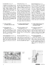
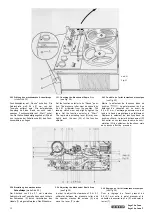
2.24 Einstellung des mechanischen
Schnellstops (siehe Abb. 14)
Der Abstand von 0.4 ± 0,1 mm zwischen An-
druckrolle und Tonwelle kann nach Lockern
der Schraube (F) durch Verdrehen des
Exzenters (G) eingestellt werden.
Das Mitnahmemoment der rechten Kupplung
wird durch Biegen der Schaltstange (Y) so
eingestellt, daß das Band in Stellung
„Pause" bzw. bei elektrischem Schnellstop
nur noch wenig gespannt ist.
2.24 Adjusting the Mechanical Rapid Stop
(see Fig. 14)
The clearance of 0.4 ± 0.1 millimeter be-
tween the pressure roller and the capstan
can be adjusted after slackening the screw
(F) by twisting the cam (G).
The driving moment of the right-hand clutch
is adjusted by bending the actuating rod (Y)
in such a manner that the tape is only under
slight tension in position "Pause" or in con-
junction with the electric rapid stop.
2.24 Réglage de l'arrêt instantané mécanique
(voir fig. 14)
Pour le réglage de l'écart prescrit (0,4 +
0,1 mm) entre le galet presseur et le cabe-
stan, desserrer la vis (F) et décaler l'excen-
trique.
Par le cambrage de la tringle de commande
(Y), ajuster le couple d'entraînement de l'em-
brayage droit de manière que la bande ne
soit que faiblement tendue en régime
«Pause», resp. en régime d'arrêt instantané
électrique.
2.3 Bandführungen
Die Einstellung der Bandführungen am
kopfträger ist beim Umrüsten von Vierspur
auf Zweispur oder.umgekehrt nicht erforder-
lich. Sie kann erst nach Austausch von Teilen
im Tonkopfträger notwendig werden.
2.3 Tape Guides
When the recorder is converted from 4-track
operation to 2-track operation or vice versa,
the tape guides near the head assembly
need not be readjusted. Readjustment will
only the necessary after replacement of
parts in the head assembly.
2.3 Guide-bande
Le réglage des guide-bande sur l'unité de
têtes magnétiques n'est pas nécessaire lors
de l'échange de l'unité «quatre pistes» contre
l'unité
ou vice versa. Il n'est à
prévoir qu'après l'échange de certaines
pièces détachées dans l'unité des têtes
magnétiques.
2.31 Prüfung
Vordere Tonkopfabdeckung abziehen. Ton-
band einlegen. Gerät in Betrieb setzen und
auf Stellung „Start" schalten. Das Tonband
muß ohne an den oberen und unteren Be-
grenzungen der Bandführungen zu streifen,
durchlaufen.
2.31 Checking
Pull off the front sound head cover, thread
the tape. Turn on the recorder and set for
"Start". The tape must pass the upper or
lower limits of the tape guides without touch-
ing.
2.31 Contrôle
Retirer la coiffe avant de l'unité de tètes
magnétiques. Insérer une bande, enclencher
le magnétophone et mettre le sélecteur de
fonctions dans sa position «Start». La bande
doit passer exactement entre les limites
supérieure et inférieure des guides, sans les
effleurer.
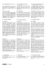
2.32 Einstellung (siehe Abb. 15)
Bezugspunkt für die Einstellung sind die in
ihrer Höhe unveränderlichen äußeren Band-
führungen. Die Bandführungsrolle (C) zwi-
schen Dia-Pilot-Kopf (A) und Aufnahmekopf
wird durch Verstellen der selbstsichernden
Mutter (T) auf richtige Höhe gebracht. —
Nach Lockern der Kontermutter (D) wird
durch Drehen der Schraube (E) die Band-
führung (F) neben dem Wiedergabekopf ein-
gestellt.
2.32 Adjusting (see Fig. 15)
The outer tape guides, whose height can-
not be adjusted, serve as point of reference
for the adjustment. Set the tape guide pulley
(C) between the Dia-Pilot-Head (A) and the
recording head to the correct height by ad-
justing the self-locking nut (T). The tape
guide (F), which is located close to the play-
back head, is adjusted after slackening the
check nut (D) by turning the screw (E).
2.32 Réglage (voir fig. 15)
Pour les opérations de réglage, il convient
de se référer aux guide-bande d'extrémité
dont la hauteur est invariable.
Le guide-bande (C) — entre la tête de com-
mande du Dia-Pilot(A) et la tête d'enregistre-
ment — est amené sur sa hauteur correcte à
l'aide de l'écrou auto-bloquant (T).
Le guide-bande (F) — à côté de la tête d'ef-
facement—est règle à l'aide de la vis (E),
après le desserrage du contre-écrou (D).
2.4 Kopfträger (siehe Abb. 1 5)
Eine Einstellung der Köpfe am Kopfträger
ist beim Umrüsten von Vierspur auf Zwei-
spur oder umgekehrt nicht erforderlich. Die
Kopfträger sind bereits optimal justiert.
Zum Auswechseln eines Kopfes ist die ent-
sprechende Befestigungsmutter (G), (H) oder
(I) zu lösen, um den auf einer
sitzenden Kopf ausbauen zu können. Beim
Einbau ist die Befestigungsmutter so stark
anzuziehen, daß die darunterliegende Feder
vorgespannt wird. Abschließend ist die Stel-
lung aller Köpfe zu prüfen und gegebenen-
falls eine Einstellung in untenstehender
Reihenfolge vorzunehmen.
2.4 Head Support Assembly (see Fig. 15)
When the recorder is converted from 4-track
operation to 2-track operation or vice versa,
readjustment of the heads will not be neces-
sary. The head assemblies have already been
very precisely adjusted in the factory.
order to replace a magnetic head, slacken
the corresponding retaining nut (G), (H) or
(I) and remove the head, which is mounted
on a mounting bracket. When installing the
new head, the retaining nut must be tighten-
ed sufficiently tight to pretension the spring
below. Finally, the positions of all heads must
be checked and, if necessary, readjusted in
the manner described below.
2.4 Têtes magnétiques (voir fig. 15)
Le réglage des têtes magnétiques n'est pas
nécessaire lors de l'échange de l'unité
«quatre pistes» contre l'unité «bipiste» ou
vice versa, du fait que les unités de têtes
magnétiques sont soumises à un ajustage
optimal au cours de la fabrication.
Pour l'échange d'une tête magnétique, des-
serrer l'écrou de fixation respectif (G), (H) ou
(I) et retirer la tête agencée sur une platine.
Lors de la mise en place de la nouvelle tête,
serrer à fond l'écrou de fixation de manière
que le ressort sous-jacent soit tendu. Il con-
tient ensuite de vérifier la position de toutes
les têtes magnétiques et de procéder éven-
tuellement à un réglage dans l'ordre de suite
suivant.
13
SG 560 Royal


