background image

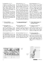
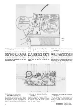
2.43 Aufnahmekopf (siehe Abb. 15)

Tongenerator an die Kontakte 1/2 und 4/2
(2 = Masse) der Buchse „Radio/Phono" an-

schließen. Je ein NF-Voltmeter (Ri > 10
an die Kontakte 1/6 und 5/6 (6 = Masse) der
Buchse „Projektor" anschließen. Tonband
einlegen, Bandgeschwindigkeit 19 cm/s ein-
schalten und Gerät in Betriebsstellung „Auf-
nahme" bringen. Die Taste „Mithören" darf

nicht gedrückt werden!

Vom Tongenerator werden jetzt 1000 Hz mit

ca. 50 mV eingespeist. Durch gleichmäßiges

Drehen der Schrauben (N) und (O) wird an

den beiden NF-Voltmetern ein Maximum ein-
gestellt. Damit ist die richtige Höhe des
Kopfes eingestellt. — Jetzt werden vom
generator 10 kHz mit ca. 50 mV eingespeist.

Durch Drehen der Schraube (P) wird an den
beiden NF-Voltmetern ein Maximum einge-

stellt. Damit ist die Senkrechtstellung des
Aufnahmekopfes erreicht.

2.43 Recording Head (see Fig. 15)

Connect an audio oscillator across the con-
tacts 1 and 2 as well as across the contacts
4 and 2 respectively (2 = ground) of the

"Radio/Phono" socket. Connect one AF volt-

meter (Zi > 10 MQ) each across the con-
tacts 1 and 6 as well as 5 and 6 respec-
tively (6 = ground) of the "Projector"
socket. Thread the tape and set the re-
corder for 7 1/2 ips and for recording opera-
tion. Do not depress the "Monitor" button!

Now feed a test signal of 1,000 Hz at ap-

proximately 50 millivolts from the audio oscil-
lator. Simultaneously turn the screws (N) and
(O) by equal amounts for maximum readings
of the two connected vacuum tube AF volt-
meters. Then the height of the head is pro-
perly adjusted. Now feed in a test signal of

10 kHz at approximately 50 millivolts from the
audio oscillator. Turn the screw (P) for maxi-
mum readings of both vacuum tube AF volt-
meters. Thus, proper azimuth adjustment of

the recording head has been accomplished.

2.43 Tête d'enregistrement (voir fig. 15)

Brancher un générateur BF sur les contacts

1-2 et 4-2 (2 = masse) de la prise -Radio/
Phono». Raccorder un voltmètre BF (Ri >
10 MQ) sur les contacts 1-6 et respective-
ment 5-6 (6 = masse) de la prise «Projec-
teur». Insérer une bande magnétique, mettre

le sélecteur de vitesses dans sa position
«19 cm/s» et enclencher le magnétophone
en régime

 Ne pas en-

foncer la touche «Monitor»!

Appliquer un signal de 1000 Hz à environ

50 mV. Par le desserrage ou le serrage
uniforme des vis (N) et (O), régler le signal
des deux voltmètres sur sa tension de sortie
maximale. La hauteur correcte de la tête
d'enregistrement est ainsi obtenue. Appliquer
ensuite un signal de 10 kHz à environ 50 mV
et le régler sur sa tension de sortie maximale
à l'aide de la vis (P). La tête d'enregistrement
est alors ajustée dans sa position verticale.

2.5 Prüfung und Einstellung

der Kontaktfedersätze und Schalter

2.5 Checking and Adjusting the Contact

Spring Assemblies and Switches

2.5 Contrôle et réglage des jeux de lames

de contact et
de correction à la lecture

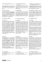
2.51 Stummkontakte K 1/K 2

und Kontakt K 7 (siehe Abb. 16)

Die beiden Stummkontakte K1 und K 2
müssen so justiert sein, daß sie nur in Stel-
lung „Stop" des Funktionswählers schließen.
Der Kontakt K7 muß in dieser Stellung ge-
öffnet sein. Die Einstellung kann nach Lok-
kern der Schraube (A) erfolgen.

2.51 Short-Circuit Contacts K 1 / K 2

and Contact K 7 (see Fig. 16)

The short-circuit contacts K1 and K2 must
be adjusted in such a manner that they will
only close in position "Stop". Contact K7

must be open in this position. After the

slackening of screw (A), the adjustment can
be made.

2.51 Contacts de court-circuit K 1/K 2

et contact K 7 (voir fig. 16)

Les deux contacts de court-circuit K1 et K 2

doivent être ajustés de manière qu'ils ne se
ferment que dans la position «Stop» du
sélecteur de fonctions. Dans cette position,

le contact K 7 doit être ouvert. Le réglage

s'opère par le desserrage de la vis (A).

2.52 Endabschaltkontakt K 3 (siehe Abb. 17)

Der Endabschaltkontakt K 3 ist nur in Stel-
lung „Start" des Funktionswählers geöffnet.
Er muß beim Drehen über die Stellung „Start"
hinaus ebenso schließen, wie in Stellung

„Pause" und "Stop". Die Einstellung kann

nach Lockern der Schrauben (A) und (B) er-
folgen.

2.52 Final Cut-Off Contact K 3 (see Fig. 17)

Final cut-off contact K 3 is only open in the
position "Start" of the function selector. It
must close equally when being turned past
the "Start" position, as in positions "Pause"

and "Stop". After slackening the screws (A)
and (B), the adjustment can be made.

2.52 Contact d'arrêt automatique

en fin de bande (K 3) (voir fig. 17)

Le contact d'arrêt automatique en fin de
bande (K 3) ne doit être ouvert que dans la
position «Start» du sélecteur de fonctions.

Il doit se fermer dans les positions

et «Stop» du sélecteur de fonctions, ainsi
que dans la position extrême droite de ce
sélecteur, au-delà de la position -Start». Le

réglage s'opère par le desserrage des vis
(A) et (B).

Abb. 16

Fig. 16

Abb. 17

Fig. 17

15

SG 560 Royal

Summary of Contents for Royal de Luxe

Page 1: ...Schutzgeb hr DM 5...

Page 2: ...cking and Adjusting 1 6 Contr le et r glage de 8 the Wind on Clutch 8 l embrayage enrouleur 8 1 7 Checking and Adjusting the Brakes 9 1 7 Contr le et r glage des freins 9 9 9 10 11 12 12 13 13 15 16 1...

Page 3: ...nordnung die bei allen Betriebsarten und in allen Betriebsstellungen wirksam ist wird als Bandzugkomparator bezeichnet Zum Verst ndnis der Arbeitsweise des Band zugkomparators ist zun chst der Aufbau...

Page 4: ...ateur de bande et du m canisme d entrainement est expliqu e et repr sent e ci dessous en r gime Pause Start D filement acc l r avant et D filement acc l r arri re 1 11 Pause siehe Abb 1 Die auf der Ac...

Page 5: ...er M onto the thrust disk G which makes the friction within the clutch great enough to en able the clutch to transmit the entire torque provided by the friction wheel R The sens ing lever I keeps the...

Page 6: ...sing lever I controls the braking ac tion of the pay out clutch as a function of the diameter of the tape roll and thus keeps the tape tension constant When disconnecting in position Rewind the tape s...

Page 7: ...thus regulating the torque or braking action respectively of the corresponding turntable The friction within the clutches is adjusted on the basis of a tape tension measurement by adjusting the compa...

Page 8: ...clean or in a new condition and that the coupling surfaces of the pres sure disks are in a satisfactory state 1 41 Checking The tape tension comparator is checked on the basis of measurements of the...

Page 9: ...nsing lever If the tension is too strong the flap must be bent towards the sensing lever The nominal values 35 5 p during Fast Forward and Fast Rewind must result from the above adjust ments 1 5 Check...

Page 10: ...istances from the left hand friction wheel D and the right hand thrust disk M These clearances can be adjusted by bending the fla N of the adjusting plate H 1 56 Adjusting the Holding Magnet for Fast...

Page 11: ...cambrage ad quat de l ergot R 1 7 Contr le et r glage des freins 1 71 Contr le Les freins travaillent en fonction du sens de d filement de la bande magn tique et agis sent sur les plateaux presseurs...

Page 12: ...nter Lift the driving belt from the groove of the driving wheel on the digital counter Then the belt can be pulled from the groove in the turntable Install the new driving belt in re verse order 1 83...

Page 13: ...ichtige Stellung des Reibrades wie unter Abs 1 91 beschrieben zu kontrollieren 1 92 Adjusting see Fig 14 In order to adjust the friction idler A slacken the check nut B and turn the set screw C When t...

Page 14: ...st the capstan is effected in position Start After slackening of the check nut L the pressure may be increased by turning the set screw M clockwise Adjust a clearance of 0 5 mm approx 0 02 relative to...

Page 15: ...rer une bande enclencher le magn tophone et mettre le s lecteur de fonctions dans sa position Start La bande doit passer exactement entre les limites sup rieure et inf rieure des guides sans les effle...

Page 16: ...en arri re de la t te Dans la version quatre pistes ou bipiste de l unit des t tes magn tiques la t te de commande du Dia Pilot doit tre ajust e de mani re que l ar te inf rieure de son entrefer se tr...

Page 17: ...r le signal des deux voltm tres sur sa tension de sortie maximale La hauteur correcte de la t te d enregistrement est ainsi obtenue Appliquer ensuite un signal de 10 kHz environ 50 mV et le r gler sur...

Page 18: ...se of operating faults The greases and oils to be used have been listed in the UHER set of lubricants Order No 09046 2 61 Lubrification Tous les organes qui ex cutent un mouve ment de rotation sont po...

Page 19: ...4 track 56 dB 2 track Attenuation of erasure 7 1 2 ips 72 dB 1000 Hz Generator frequency 100 kHz 10 Crosstalk attenuation 60 dB mono 45 dB stereo Input microphone 0 12 mV to 70 mV max Input radio 1 2...

Page 20: ...e r t in Pfeilrichtung aus der Holzzarge heraus schwenken The Service Instruction for the model UHER SG 560 Royal also applies to the models UHER Royal de Luxe and UHER Royal de Luxe C The paragraphs...

Page 21: ...ons dans sa position Pause Le galet presseur doit se d tacher du cabestan sur un cart de 0 4 0 1 mm L embrayage enrouleur ne doit tendre la bande magn tique que faiblement D placer le s lecteur de fon...

Page 22: ...oment of the right hand clutch is adjusted by bending the actuating rod H in such a manner that the tape is only under slight tension in position Pause or in con junction with the rapid stop 2 25 R gl...

Page 23: ...7 8 15 16 ips Frequency range at 7 1 2 ips 20 20 000 Hz Frequency range at 3 3 4 ips 20 15 000 Hz Frequency range at 1 7 8 ips 20 9 000 Hz Wow and flutter at 7 1 2 ips 0 05 Wow and flutter at 3 3 4 ip...

Page 24: ...4 Ohm Sinus Dauerten 2x 10 Watt Leistungsbandbreite 20 14 000 Hz bei 1 Klirrfaktor bersprechd mpfung 60 dB Fremdspannungsabstand Pegel I bei 50 mW 64 dB Pegel II bei 50 mW 69 dB bei 10 W 75 dB bei Mi...

Page 25: ......

Page 26: ......

Reviews: