background image

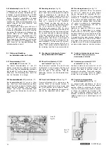
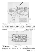
1.14 Rücklauf (siehe Abb. 3)

Von einem Hebelwerk wird das von der Mo-
torrolle (A) über den Riemen (D) getriebene

Friktionsrad (E) gegen die Druckscheibe (0)
gedrückt. Gleichzeitig wird die Bandzugstange
(S) in Pfeilrichtung bewegt. Dadurch wird die
Komparatorfeder (K) vorgespannt, die Kom-
paratorfeder (L) entspannt und die Bremse
(Q) von der Druckscheibe (O) abgehoben.
Die Bremse (P) dagegen sperrt die Druck-
scheibe (G) in ihrer gewollten Drehrichtung.
Durch die vorgespannte Komparatorfeder (K)
wird über den Fühlhebel (H) und dem Winkei-
hebel (N) ein so großer Druck auf die Druck-

scheibe (O) übertragen, daß das Mitnahme-
moment genügend groß wird, um die volle

Umspulkraft vom Friktionsrad (E) zu über-
nehmen. Der Fühlhebel (H) sorgt nunmehr
dafür, daß die für den Umspulvorgang be-
nötigte Kraftübertragung in gleicher Größe
erhalten bleibt.

Durch die entspannte Komparatorfeder (L)

wird über den Fühlhebel (I) und den Druck-
winkel (M) ein geringer Druck auf die Druck-
scheibe (G) übertragen.

Der Fühlhebel (I) sorgt jetzt dafür, daß mit
dem sich ändernden Bandwickeldurchmesser
der abwickelnden Kupplung deren Brems-
moment geregelt und damit der Bandzug kon-

stant gehalten wird.

Beim Abschalten der Stellung „Rücklauf"
bleibt das Tonband stehen, weil die fördernde
Kraft des Friktionsrades (E) aufgehoben wird
und die rechte gesperrte Druckscheibe (G)
die Kupplungsscheibe abbremst.

1.14 Rewind (see Fig. 3)

The friction wheel (E) which is driven by the

motor pulley (A) via the belt (D) is pressed
against the thrust disk (O) by means of a
lever system. Simultaneously, the tape ten-
sion rod (S) is moved in the direction of the
arrow. In this manner the comparator spring
(K) is being pretensioned, the comparator
spring (L) is being relaxed and the brake (Q)

is lifted from the thrust disk (O), whereas the
brake (P) blocks the rotation of the thrust
disk (G). Due to this pretensioned state of
the comparator spring (K), a force is exerted

via the sensing lever (H) and the angular
thrust lever (N) onto the thrust disk (O) which
makes the friction within the clutch great
enough to enable the clutch to transmit the
entire rewinding torque provided by the fric-
tion wheel (E). The sensing lever (H) keeps
the rewinding torque constant.
Due to the relaxed state of the comparator
spring (L) only a small force is exerted on
the thrust disk (G) via the sensing lever (I)
and the angular thrust lever (M).
The sensing lever (I) controls the braking ac-
tion of the pay-out clutch as a function of the
diameter of the tape roll and thus keeps the

tape tension constant.
When disconnecting in position "Rewind",

the tape stops, since the driving force of

friction pulley (E) is cancelled and the right-
hand blocked pressure disk (G) brakes the
clutch disk.

1.14 Régime -Défilement accéléré arrière»

(voir fig. 3)

Un système de leviers presse la roue à fric-
tion (E) — entraînée par la poulie (A) du
moteur et par la courroie (D) — contre le
plateau presseur (O). En même temps, la
barre de traction (S) est déplacée dans le
sens de la flèche. A la suite de ce mouve-
ment, le ressort (K) est tendu, le ressort (L)
se détend et le frein (Q) du plateau presseur
(O) se soulève. Le frein (P) bloque par con-

tre le plateau presseur (G) dans le sens de

rotation spontané. Par l'intermédiaire du le-

vier palpeur (H) et du levier coudé (N), le
ressort tendu (K) transmet une si grande
force sur le plateau presseur (O), que le
couple d'entraînement est suffisant pour
reprendre le plein effort de bobinage de la
roue à friction (E). Le levier palpeur (H) dose

alors la force nécessaire à transmettre pour
le réembobinage de la bande.

Le ressort (L) étant détendu, il ne transmet

qu'une faible force sur le plateau presseur
(G) par l'intermédiaire du levier palpeur (I)
et du levier coudé (M). A son tour, le levier

palpeur (I) dose le couple de freinage de

l'embrayage dérouleur en fonction de la
longueur de bande encore disponible sur la
bobine, ce qui stabilise la traction exercée
sur la bande.

A l'arrêt du

 accéléré arrière», la

bande magnétique s'immobilise, du fait que
la force motrice de la roue à friction (E) est
supprimée et que le plateau presseur droit
(G) bloqué freine le disque d'embrayage.

Abb. 3

Fig. 3

1.2 Kupplungen (siehe Abb. 4)

Im Aufbau der Kupplungen besteht kein

Unterschied. Sie setzen sich aus folgenden

Teilen zusammen:

1.2 Clutches (see Fig. 4)

The two clutches are of identical design.

Each clutch consists of the following parts:

1.2 Embrayages (voir fig. 4)

Les deux embrayages ont une structure iden-
tique et se composent des pièces suivantes:

A Spulenteller A Turntable

B Mitnehmerstift B Driving pin
C Beilagscheibe C Shim plate
D Oberes Kugellager D Upper ball bearing
E Chassis E Chassis
F Unteres Kugellager F Lower ball bearing
G Kupplungsscheibe G Clutch disk
H Sternfeder H Star-shaped spring

 SG 560 Royal

A Plateau de bobine

B Broche d'entraînement
C Rondelle d'épaisseur
D Roulement à billes supérieur
E Cage
F Roulement à billes inférieur
G Disque d'embrayage
H Ressort étoile

Summary of Contents for Royal de Luxe

Page 1: ...Schutzgeb hr DM 5...

Page 2: ...cking and Adjusting 1 6 Contr le et r glage de 8 the Wind on Clutch 8 l embrayage enrouleur 8 1 7 Checking and Adjusting the Brakes 9 1 7 Contr le et r glage des freins 9 9 9 10 11 12 12 13 13 15 16 1...

Page 3: ...nordnung die bei allen Betriebsarten und in allen Betriebsstellungen wirksam ist wird als Bandzugkomparator bezeichnet Zum Verst ndnis der Arbeitsweise des Band zugkomparators ist zun chst der Aufbau...

Page 4: ...ateur de bande et du m canisme d entrainement est expliqu e et repr sent e ci dessous en r gime Pause Start D filement acc l r avant et D filement acc l r arri re 1 11 Pause siehe Abb 1 Die auf der Ac...

Page 5: ...er M onto the thrust disk G which makes the friction within the clutch great enough to en able the clutch to transmit the entire torque provided by the friction wheel R The sens ing lever I keeps the...

Page 6: ...sing lever I controls the braking ac tion of the pay out clutch as a function of the diameter of the tape roll and thus keeps the tape tension constant When disconnecting in position Rewind the tape s...

Page 7: ...thus regulating the torque or braking action respectively of the corresponding turntable The friction within the clutches is adjusted on the basis of a tape tension measurement by adjusting the compa...

Page 8: ...clean or in a new condition and that the coupling surfaces of the pres sure disks are in a satisfactory state 1 41 Checking The tape tension comparator is checked on the basis of measurements of the...

Page 9: ...nsing lever If the tension is too strong the flap must be bent towards the sensing lever The nominal values 35 5 p during Fast Forward and Fast Rewind must result from the above adjust ments 1 5 Check...

Page 10: ...istances from the left hand friction wheel D and the right hand thrust disk M These clearances can be adjusted by bending the fla N of the adjusting plate H 1 56 Adjusting the Holding Magnet for Fast...

Page 11: ...cambrage ad quat de l ergot R 1 7 Contr le et r glage des freins 1 71 Contr le Les freins travaillent en fonction du sens de d filement de la bande magn tique et agis sent sur les plateaux presseurs...

Page 12: ...nter Lift the driving belt from the groove of the driving wheel on the digital counter Then the belt can be pulled from the groove in the turntable Install the new driving belt in re verse order 1 83...

Page 13: ...ichtige Stellung des Reibrades wie unter Abs 1 91 beschrieben zu kontrollieren 1 92 Adjusting see Fig 14 In order to adjust the friction idler A slacken the check nut B and turn the set screw C When t...

Page 14: ...st the capstan is effected in position Start After slackening of the check nut L the pressure may be increased by turning the set screw M clockwise Adjust a clearance of 0 5 mm approx 0 02 relative to...

Page 15: ...rer une bande enclencher le magn tophone et mettre le s lecteur de fonctions dans sa position Start La bande doit passer exactement entre les limites sup rieure et inf rieure des guides sans les effle...

Page 16: ...en arri re de la t te Dans la version quatre pistes ou bipiste de l unit des t tes magn tiques la t te de commande du Dia Pilot doit tre ajust e de mani re que l ar te inf rieure de son entrefer se tr...

Page 17: ...r le signal des deux voltm tres sur sa tension de sortie maximale La hauteur correcte de la t te d enregistrement est ainsi obtenue Appliquer ensuite un signal de 10 kHz environ 50 mV et le r gler sur...

Page 18: ...se of operating faults The greases and oils to be used have been listed in the UHER set of lubricants Order No 09046 2 61 Lubrification Tous les organes qui ex cutent un mouve ment de rotation sont po...

Page 19: ...4 track 56 dB 2 track Attenuation of erasure 7 1 2 ips 72 dB 1000 Hz Generator frequency 100 kHz 10 Crosstalk attenuation 60 dB mono 45 dB stereo Input microphone 0 12 mV to 70 mV max Input radio 1 2...

Page 20: ...e r t in Pfeilrichtung aus der Holzzarge heraus schwenken The Service Instruction for the model UHER SG 560 Royal also applies to the models UHER Royal de Luxe and UHER Royal de Luxe C The paragraphs...

Page 21: ...ons dans sa position Pause Le galet presseur doit se d tacher du cabestan sur un cart de 0 4 0 1 mm L embrayage enrouleur ne doit tendre la bande magn tique que faiblement D placer le s lecteur de fon...

Page 22: ...oment of the right hand clutch is adjusted by bending the actuating rod H in such a manner that the tape is only under slight tension in position Pause or in con junction with the rapid stop 2 25 R gl...

Page 23: ...7 8 15 16 ips Frequency range at 7 1 2 ips 20 20 000 Hz Frequency range at 3 3 4 ips 20 15 000 Hz Frequency range at 1 7 8 ips 20 9 000 Hz Wow and flutter at 7 1 2 ips 0 05 Wow and flutter at 3 3 4 ip...

Page 24: ...4 Ohm Sinus Dauerten 2x 10 Watt Leistungsbandbreite 20 14 000 Hz bei 1 Klirrfaktor bersprechd mpfung 60 dB Fremdspannungsabstand Pegel I bei 50 mW 64 dB Pegel II bei 50 mW 69 dB bei 10 W 75 dB bei Mi...

Page 25: ......

Page 26: ......

Reviews: