background image

1.83 Austausch des Antriebsrades

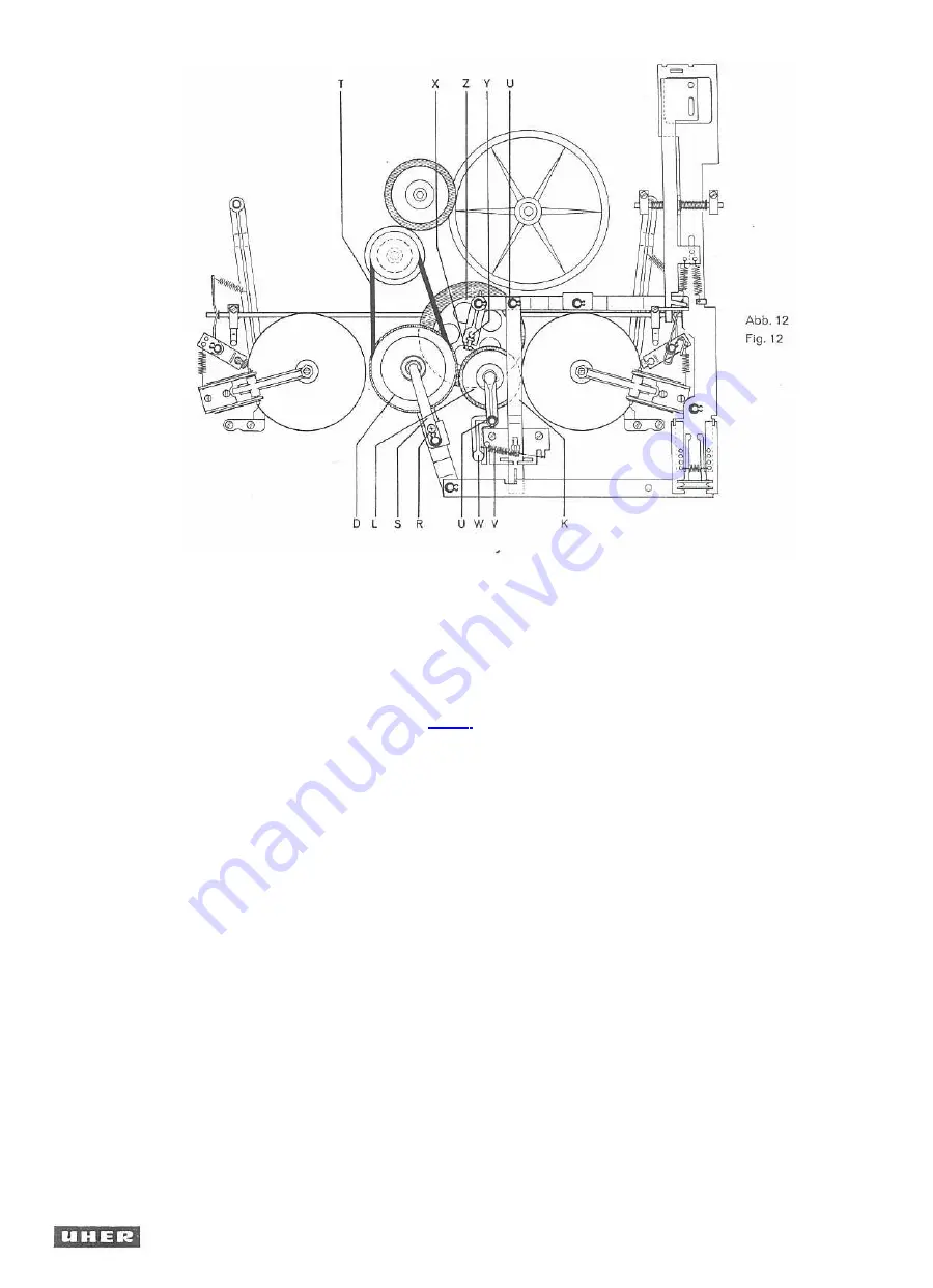
(siehe Abb. 12)

Linkes Friktionsrad (D) gemäß Abs. 1.81 aus-
bauen, Schraube (X) lockern und Achse (Y)
nach oben herausziehen. Das Antriebsrad (Z)

kann jetzt leicht ausgetauscht werden. Der
Einbau ist sinngemäß in umgekehrter Reihen-

folge vorzunehmen. Es ist darauf zu achten,

daß die Achse (Y) so weit eingeschoben wird,
dar' das Axialspiel des Antriebsrades ca.

' mm beträgt.

1.84 Austausch des Antriebsriemens

zum linken Friktionsrad (siehe Abb. 12)

Nach Entfernen der Schraube (R) und Aus-
schwenken des Haltestreifens (S) kann der

Antriebsriemen (T) aus den Laufrillen ge-

hoben und ausgetauscht werden. Der Einbau

i st sinngemäß in umgekehrter Reihenfolge

vorzunehmen.

1.85 Austausch des Antriebsriemens

zum Bandzählwerk

Der

Antr

iebsriemen wird aus der Laufrille

des Antriebsrades am Bandzählwerk geho-
ben. Mit einer Pinzette laßt sich nunmehr

der Riemen aus der Laufrille im Spulenteller
herausziehen- Der Einbau ist sinngemäß in
umgekehrter Reihenfolge vorzunehmen.

1.9

Prüfung und Einstellung

des Bandgeschwindigkeitswählers

Die Umschaltung der Bandgeschwindigkeit
erfolgt durch Verändern des Übersetzungs-
verhältnisses

des

Reibradgetriebes.

Das

Reibrad wird mit einer der vier Stufen der
Motorrolle in Friktion gebracht und über-

1.83 Replacing the Drive Wheel (säe Fig. 12)

Remove the left-hand friction wheel (D) ac-
cording to paragraph 1.81, slacken the screw
(X) and pull out the shaft (Y) in an upward
direction. The friction idler (Z) can now
easily be replaced. Install the new friction
i dler in reverse

order. l t

is important to slide

i n the shaft (Y) far enough as to adjust an
axial play of the drive wheel of approxima-
tely 0.1 millimeter.

1.84 Replacing the Driving Belt for the

Left-Hand Friction Wheel (see Fig. 12)

Remove the screw (R) and swing aside the
flat spring (S). Now the driving belt (T) can
be removed from the grooves of the motor
pulley and the left-hand friction wheel. In-
stall the new driving belt in reverse order.

1.85 Replacing the Driving Belt

for the Digital Counter

Lift the driving belt from the groove of thc

driving wheel an the digital Counter. Then the
belt can be pulled from the groove in the

turntable. Install the new driving belt in re-
verse order.

1.9 Checking and Adjusting

the Tape Speed Selector

The different tape speeds are selected by
changing the reduction ratio of the friction
gear. The friction wheel is made to engage

one of the four steps of the motor pulley and
thus transmits the torque to the flywheel.

1.83 Echange de la roue d'entrainement

(voir fig. 12)

Dämonter la roue ä friction gauche (D) com-
me däcrit sous 1.81, desserrer la vis (X) et

sortir vers le haut faxe (Y). L'echange de la

roue d'entrainement (Z) s'opäre alors aise-

ment. Procäder au remontage dens fordre

de suite inverse. L'axe (Y) doit etre repoussä

suffisamment, afin que la roue d'entraine-

ment ait un jeu axial d'environ 0.1 mm.

1.84 Echange de la courroie d'entrainement

de la roue ä friction gauche (voir fig. 12)

Degager la vis (R) et detourner la barrette
de retenue (S). Sortir la courroie d'entraine-

ment (T) qui relie la poulie du rrioteur ä la

roue (D). Remonter la nouvelle courroie dans
fordre de suite inverse.

1.85 Echange de la courroia d'entrainement

du compteur

Sortir la courroie hors de la gorge de la roue
d'entrainement du compteur, puis avec des
pincettes, hors de la gorge de roulement du
plateau de la bobine. Procäder au remontage
dans fordre de suite inverse,

1.9

Contrdle et räglage du selecteur
de vitesses

La commutation des vitesses de däfilement
s'opere par la modification du rapport de
transmission de I'embrayage ä friction. La
roue ä friction s'engage dans un des quatre
gradins de la poulie du moteur et transmet

SG 560 Royal

1 0

Summary of Contents for SG 560 Royal

Page 1: ...SG 560 ROYAL ROYAL de Luxe ROYAL de Luxe C Schutzgeb hr DM 5...

Page 2: ...chapitre constitue en lui m me un tout in d pendant et peut donc tre consult s par ment seien las travaux ex cuter sur le magn tophone II s ensuit que de chapitre en chapitre certaines r p titions son...

Page 3: ...r pulley A and the flywheel C In the position Amplifier of the tape speed selector the motor la disconnected The special design of the transport mecha nism allows the recorder to be operated in a hori...

Page 4: ...r de bande et du mecanisme d entrainement est expliquee et representee ci dessous en regime Pause Start Defilement accelere avant et De filement accelere arriere 1 11 Pause siehe Abb 1 Die auf der Ach...

Page 5: ...r M onto the thrust disk G which makes the friction within the clutch great enough to en able the clutch to transmit the entire torque provided by the friction wheel R The sens ing lever I keeps the w...

Page 6: ...ing lever I controls the braking ac tion of the pay out clutch as a function of the diameter of the tape roll and thus keeps the tape tension constant When disconnecting in position Rewind the tape st...

Page 7: ...regulating the torque or braking action respectively of the corresponding turntable The friction within the clutches is adjusted an the basis of a tape tension measurement by adjusting the comparator...

Page 8: ...e et reglage du comparateur de tension de la bande Avant d entreprendre le contr le et le regla ge du comparateur de tension de la bande il convient de nettoyer avec de Talcool les courroies de caoutc...

Page 9: ...zug komparatoren siehe Abs 1 4 1 5 Checking and Adjusting the Fast Forward and Rewind Functions The fast forward and rewind functions will not perform properly unless the tape tension comparator is co...

Page 10: ...at equal distances from the left hand friction wheel D and the right hand thrust disk M These clearances can be adjusted by bending the fla r N of the adjusting plate H 1 56 Adjusting the Holding Magn...

Page 11: ...ration slacken the screws O and slide the actua tor P as far as to litt the left hand brake Q by 1 5 2 millimeters The right hand brake is adjusted in an analo gous manner while the recorder is sei fo...

Page 12: ...ve the screw R and swing aside the flat spring S Now the driving belt T can be removed from the grooves of the motor pulley and the left hand friction wheel In stall the new driving belt in reverse or...

Page 13: ...ge Stellung des Reibrades wie unter Abs 1 91 beschrieben zu kontrollieren 1 92 Adjusting see Fig 14 In order to adjust the friction idler A slacken the check nut B and turn the s t screw C When the sp...

Page 14: ...ed in position Start After slackening of the check nut L the Pressure may be increased by turning the set screw M clockwise Adjust a clearance of 0 5 mm approx 0 02 relative to the stop P an the mount...

Page 15: ...ee Fig 15 The outer tape guides whose height can not be adjusted serve as point of reference for the adjustment Set the tape guide pulley C between the Dia Pilot Head A and the recording head to the c...

Page 16: ...r the UHER Four Track Test Tape as the case may be Connect LF voltmeter Zi 10 MOhm to con tacts 3 and 2 2 chassis of the Radio Phono socket Thread the UHER Test Tape wind and rewind the entire length...

Page 17: ...for maxi mum readings of both vacuum tube AF volt meters Thus proper azimuth adjustment of the recording head has been accomplished 2 5 Checking and Adjusting the Contact Spring Assemblies and Switch...

Page 18: ...f lubricants since surplus grease or oll may reach friction lin ings or drive belts and then will undoubtedly be the sause of operating faults The greases and oils to be used have been listed in the U...

Page 19: ...to noise ratio at 1 7 8 ips 52 dB 4 track 56 dB 2 track Attenuation of erasure 7 1 2 ips 72 dB 1000 Hz Generator frequency 1 00 kHz 10 0 0 Crosstalk attenuation 60 dB mono 45 dB stereo Input microphon...

Page 20: ...n Pfeilrichtung aus der Holzzarge heraus schwenken 1 85 Austausch des Antriebsriemens zum Bandz hlwerk Zum Austausch des Antriebsriemens sind zweckm igerweise die Bedienungskn pfe und die Abdeckplatte...

Page 21: ...sa position Pause Le galet presseur doit se detacher du cabestan sur un ecart de 0 4 0 1 mm L embrayage enrouleur ne doit tendre la bande magnetique que faiblement Deplacer le selecteur de fonctions d...

Page 22: ...ement R la tringle de commande Y le levier X et le levier palpeur droit Le cas echeant le couple d entrainement peut etre modifie par le cambrage de la tringle de com mande Y et de I ergat Z 2 25 Regl...

Page 23: ...s Frequency range at 71 2 ips 20 20 000 Hz Frequency range at 3 3 4 ips 20 15 000 Hz Frequency range at 1 7 8 ips 20 9 000 Hz Wow and flutter at 7 1 2 ips 0 05 Wow and flutter at 3 3 4 ips 0 10 Wow an...

Page 24: ...ower across 4 Ohm sinusoidal continuous tone 2X10W Power bandwidth 20 to 14 000 Hz wich 1 harmonic distortion Crosstalk attenuation 60 dB S N ratio unweighted level I at 50 mW 64 dB level 11 at 50 mW...

Reviews: