


digital
2
Lokdecoder 74 320
by Lenz Elektronik GmbH
This decoder also includes the description and programming instructions of the Intelidrive 2 mini decoder
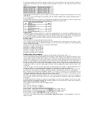
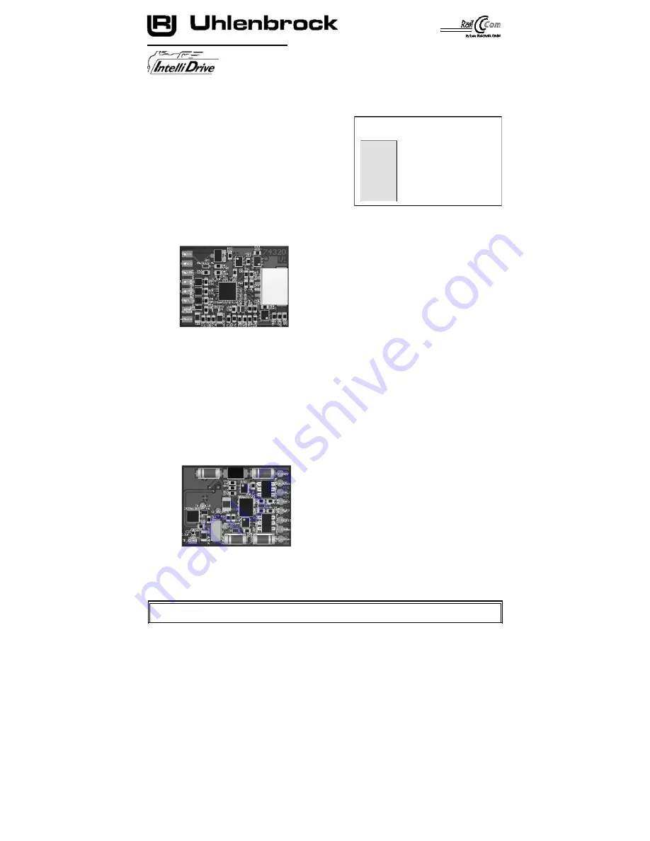
Connections of the locomotive decoder 74 320
Remove the bridge connector from the interface socket
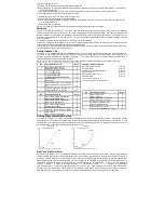
Pin assignment of the interface
your vehicle. In the same place, plug the plug
according to NEM 652 for DCC decoder
1 Motor connection (orange)
of the locomotive decoder carefully into the interface socket.
Is a contact on the interface socket in the vehicle with
1
8
2 Rear lighting (yellow)
a 1" marked, then the pin on which the red cable
2
7
3 Special function A1 (green)
4 Power consumption left (black)
is plugged in here. Fix the decoder in place
3
6
5 Motor connection (grey)
with the included adhesive pad and make sure that also
6 Lighting front (white)
4
5
no short circuits can occur after closing the locomotive.
7
gem. Positive pole lighting (blue)
The first commissioning should take place on the programming
track
8 Power consumption right (red)
when the programming mode of the control panel is called up.
When reading or programming, very small currents usually flow, which do not damage the decoder in the
event of a short circuit.
red
orange
blue
yellow
weiß
green
grey
black
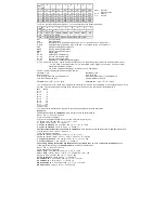
Connection of special functions
An additional special function such as smoke generator, automatic coupling or a cab lighting can be
connected to the special function output A1 (green).
Connection of incandescent lamps
To adjust the operating voltage and to avoid very high inrush currents, we recommend a resistance of 68
ohms to the incandescent lamps in series.
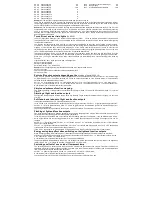
Connection of energy storage device 71800
the energy store is labeled as in its instructions
ben connected. The connection points of brown and
blue
blue line are shown on the sketch.
brown
ATTENTION:
Soldering on the decoder should only be carried out by experienced professionals with the appropriate
tools. For decoders that have been damaged by improper handling, the warranty claim is void.
A short circuit in the area of motor, lighting and power consumption
destroys the building block and possibly the electronics of the locomotive!


