


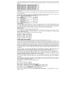

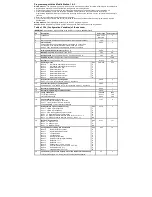

CV
Description
Value range
Value ex works
31
Pointer CV for CV banks
0,1,8
0
32
2nd pointer CV for CV banks
0, 1, 3, 4, 5,
255
255
33-46
Simple function mapping
0-255
Assignment of the function outputs to the CVs
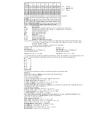
CV 33
Light function button (F0) when driving forward
1
CV 34
Light function key (F0) when reversing
2
CV 35
Function key F1
4
CV 36
Function key F2
8
CV 37
Function key F3
16
CV 38
Function key F4
32
CV 39
Function key F5
64
CV 40
Function key F6
128
CV 41
Function key F7
0
CV 42
Function key F8
0
CV 43
Function key F9
0
CV 44
Function key F10
0
CV 45
Function key F11
0
CV 46
Function key F12
0
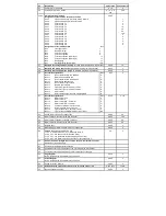
Assignment of the individual bits
Wert
Bit 0
Front light output
1
Bit 1
Rear light output
2
Bit 2
Function output A1
4
Bit 3
Function output A2
8
Bit 4
Function output A3 (SUSI/logic)
16
Bit 5
Function output A4 (SUSI/logic)
32
Bit 6
Rangiergang
64
Bit 7
Starting/braking deceleration
128
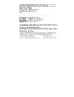
47
Motorola 1st trinary address (directly
only with Motorola programming method)
0-255
12
48
Motorola 2nd trinary address (only
with Motorola programming method)
0-255
0
49
Motorola 3rd trinary address (only
with Motorola programming method)
0-255
0
50
Decoder Konfiguration 1
Wert
0-63
0
Bit 0=0
Do not use Motorola 2nd address
0*
Bit 0=1
Motorola 2nd address use
1
Bit 1=0
Do not use Motorola 3rd address
0*
Bit 1=1
Motorola 3rd address use
2
Bit 2=0
Do not replace light outputs
0*
Bit 2=1
Replace light outputs
4
Bit 3=0
Frequency light, A1 and A2 = 156Hz
0*
Bit 3=1
Frequency light, A1 and A2 = 24KHz
8
Bit 4=0
SUSI = SUSI
0*
Bit 4=1
SUSI = A3/A4 output function mapping table
16
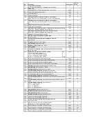
51
Decoder Konfiguration 2
Wert
0-135
3, 131
Bit 0=0
Motor control from
0
Bit 0=1
Motor control a
1*
Bit 1=0
Motor control PID - Controller
0
Bit 1=1
Motor control SX - controller
2*
Bit 2=0
no dynamic period of motor control
0
Bit 2=1
Dynamic period of motor control
4
Bit 7=0
Light, A1/A2 PluX12 decoder (73145)
0
Bit 7=1
Light, A1/A2 cable/NEM decoder (not 73145)
128
53
Period of motor control in 100µs steps
0-255
40
54
Motor control P-constant of the PID controller
0-255
100
55
Motor control I-constant of the PID controller
0-255
40
56
Motor control D-constant of the PID controller
0-255
32
57
Regler Offset
0-255
6
58
Measuring gap for EMF measurement in 100µs steps
0-255
8
59
Factory reset
(also possible via CV8)
0-4
0
1 = CV 0 - 256, and CV257 - 512 (RailCom® Bank 7)
2 = CV 257 - 512 (RailCom Plus
®
Banken 5 & 6)
3 = CV 257 - 512 (extended function mapping banks 1 & 2)
4 = CV 257 - 512 (PWM modulation function outputs banks 3 & 4)
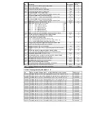
60
Short-circuit monitoring Motor, function outputs, temperature control.
-
-
Switched on (do not change)
61
Constant for the temperature shutdown
-
-
62
Constant of short-circuit detection of the FKT outputs (do not change)
-
-
63
Constant of short-circuit detection of motor output (do not change)
-
-
64
Page Register
0-255
0
for CV programming with a Motorola control unit
65
Offset-Register
0-255
0
for CV programming with a Motorola control unit
66
Speed correction forward
0-255
0
67-94
Extended speed step characteristic curve for speed steps 1 - 28
0-255 each
under.
95
Reverse speed correction
0-255
0


