


digital
by Lenz Elektronik GmbH
2
Mini-Lokdecoder 73
300, 73 310, 73 340, 73 406, 73
416
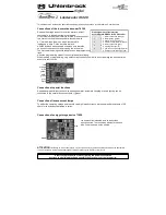
Programming
The configuration variables (CVs) form the basis of all settings of the decoder. The decoder can be programmed with the
Intellibox, DCC control panels and Motorola control panels.
Programming with the Intellibox
We recommend programming the decoder via the programming menu for DCC decoders, regardless of the format to be used
later.
The Intellibox supports DCC programming with a convenient input menu. Long addresses do not have to be calculated laboriously, they
can be entered directly. The Intellibox automatically calculates the values for CV 17 and CV 18.
Special case loco addresses 80 to 255 in Motorola data format
The Intellibox supports an address range up to 255 in the Motorola data format. For the first Motorola address, addresses 1 to 80 can
also be easily programmed via DCC programming. However, if locomotive addresses larger than 80 are to be used, the address must be
programmed in any case as in the chapter "Programming with a Märklin central station". After this programming, the CV 1 contains the
value 0 and the decoder uses the Motorola address greater than 80.
Programming with DCC devices
Use the programming menu of your DCC control panel to read and program the decoder CVs via register, CV directly or page
programming. It is also possible to program the decoder by main track programming with a DCC digital control center.
The exact procedure can be found in the manual of the used control unit.
Programming of long addresses without programming menu
If programming is performed with control panels that do not support programming with an input menu, the value for CV 17 and CV 18
must be calculated. Here the instructions for programming the address 2000.
• Divide the address value by 256 (2000:256 = 7 Rest 208).
• Take the integer result (7) and add 192.
• Enter the result (199) as a value in CV 17.
• Enter the remainder (208) as a value in CV 18.
• Important: Set bit 5 from CV 29 to 1 so that the decoder uses the long address.
Programming
lock (decoder programming lock)
The decoder programming lock is used for several decoders in a vehicle to change CVs in only one of the decoders with the
same basic address (CV1) or long address (CV17 and CV18). For this purpose, each decoder CV16 must be programmed to
a different number (index number) before the decoders are installed in the vehicle. To change or read the value of a CV in one
of the installed decoders, program the corresponding index number in CV15 and then program the CVs of the selected
decoder. The decoders compare the values in CV15 and CV16 and if both values match, access to the CVs is released. If the
comparison fails, the CVs of this decoder cannot be accessed.
The following index numbers are recommended: 1 for motor decoders, 2 for sound decoders, 3 or higher for function and
other types of decoders.
Programming with a Märklin control unit (eg
6021)
With a Märklin control panel, all CVs can be programmed, but not read out. The decoder can be put into programming mode
in two ways (a and b, depending on the control panel) and then programmed.
Switch off and on the control panel
Set control panel to "Motorola old" (6021 DIP 2 = off), switch control panel off and on
Select address of decoder and turn on light
Set central to "stop" and dial address 80
When the locomotive is stationary (speed level 0), press the direction switch 5-8 times in a row until the lighting flashes
Press and hold the change of direction when the locomotive is stationary, set the central unit to "go" and wait about 12 seconds
4. Enter the number of the CV to be programmed as a loco address at the control panel
5. Briefly press the direction switch (5a and 5b). Now the rear light flashes 4 x fast (only 5a)
6. Enter the desired value for the CV like a loco address at the central office
7. Briefly press the direction switch (7a and 7b). Now the rear light flashes 4 x slowly (only 7a)
If further CVs are to be programmed repeat point 4-7
If the programming is to be stopped, switch the control panel to "stop", or enter the address 80 and briefly press the direction
switch.
Since only inputs from 01 to 80 are possible when programming with a Motorola digital control center from Märklin, the value
0" must be entered via the address as 80".
Page register for entering CV numbers greater than 79
CV numbers greater than 79 can only be programmed using the Page tab. This page register is the CV64. If the CV64 is described with a
value greater than 0, the content of the CV64 times 64 is added to each subsequent, entered address value in all subsequent
programming operations. The entered value must be in the range 1 to 64.
After successful programming of all CVs greater than 79, the page register (CV64) must be reset to zero.
If, for example, the CV82 is to be programmed with the value 15, the CV64 must first be programmed with the value 1. Then
the CV18 can be programmed with the value 15. In the decoder, the value 15 is now stored in the CV number 82, which
results from the addition of the content of the CV64 (in example 1) multiplied by 64 (ie 64) and the entered CV number at the
control panel (18).
Offset register for entering CV values greater than 79
CV values greater than 79 can only be programmed using the offset register. This offset register is the CV65. If the CV65 is
described with a value > 0, the content of the CV65 is multiplied by 4 for all subsequent programming operations, added to
each CV value programmed below and stored in the corresponding CV.
After successful programming of all CV values greater than 79, the offset register (CV65) must be reset to zero.
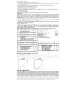
For example, if the CV49 is to be programmed with the value 157, the CV65 must first be programmed with the value 25.
Then the CV49 can be programmed with the value 57. The value 4* 25 + 57 is now stored in the decoder.
Note:
When programming the CV64 and the CV65, the content of the offset and page registers is not taken into account.


