


digital
by Lenz Elektronik GmbH
2
Mini-Lokdecoder
73 300, 73 310, 73 340 73 406, 73 416
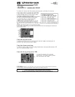
Description
This manual describes in detail the entire range of functions of your new locomotive decoder. In order to enjoy it as much as
possible, please read the instructions carefully and completely.
This locomotive decoder is a small, very powerful multi-protocol decoder. It can be used in DCC, Motorola and Selectrix digital
systems. It also runs in analog mode with DC voltage. The respective operating mode is automatically detected, but it can also
be set manually.
The decoder works with a frequency of 18.75 kHz and is therefore suitable not only for direct current, but also for
Bell armature motors (e.g., Faulhaber, Maxon, Escap) up to a continuous current consumption of 0.8 A
Motor currents up to 2 A are well tolerated.
The decoder is RailCom®
and RailCom Plus®
capable and masters both ABC braking and ABC slow-speed driving. The engine
characteristic curve is set via the minimum, medium and maximum speed (simple characteristic curve), or via the extended
characteristic curve with individual settings for 28 speed steps.
The decoder has two direction-dependent lighting outputs, as well as two additional special function outputs (not 73115). Its manoeuvring
gear with extended low-speed range and the three possible starting and braking decelerations can be switched via function keys. Ideal for
use in American locomotive models is the possibility to activate special, typical American light effects (Mars Light, Gyra Light, Strobe,
etc.).
The assignment of switching tasks such as lighting, special function outputs (not 73115), shunting and switchable driving,
braking deceleration (ABV) can be freely assigned to the function keys F0 - F12 of the digital control center (small function
mapping). In addition, the decoder also supports extended function mapping. In the extended function mapping, simultaneous
switching on or off of several outputs is possible depending on linked conditions (F-keys, direction of travel, loco stands /
moves) with a function key assignment F0 - F44.
The decoder can be programmed via all Intelliboxes, DCC and Märklin controllers. All CVs can be programmed with all
devices. To facilitate programming, especially for extended function mapping, the programming software "Lok-Tool" can be
used, which is included with the digital programming and test station "DigiTest" from Uhlenbrock. This software is also
available for free download on our website www.uhlenbrock.de.
As a further special feature, the decoder can be updated via the digital programming and test station "DigiTest" from
Uhlenbrock. It can even remain in the closed vehicle. Even the installation of locomotive sounds on a connected IntelliSound 4
module can take place in this constellation in the installed state.
IMPORTANT
: All information
about
the function outputs A1 & A2 in the user manual do not apply to the decoder 73115 with
6-pin NEM 651 interface.
Analog operation with DC voltage
The locomotive decoder is suitable for analog operation with DC voltage, which is detected
independently.
ATTENTION:
Operation with AC voltage will destroy the decoder!
NOTE: In DC mode, your vehicle will only start at a higher voltage (throttle further turned up) than you might have been used
to in operation with analog vehicles.
Function outputs in analog mode
It is possible to set the decoder so that the function keys F0 - F12, as assigned in the function mapping, can also be switched
on in analog mode. For this purpose, the CVs 13 & 14 must first be programmed with a digital control center. The
corresponding values can be found in the CV table.
Motor control
The motor control preset in the decoder is ideal for most motor types. If the driving behavior of your vehicle does not meet
your expectations, because it jerks, for example, at low speed, you can change this standard setting of the engine control.
Two control types are available for adjusting the motor control.
1. PID Regler
2. SX two-point controller
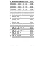
Within the CV51, the first three bits can be used to define whether a controller should be active, if yes, which controller should be active
and whether a fixed or variable period is used (see Configuration CVs -> Table CV51, Bits 0 - 2).
CV51
Bit0 -> 0 = knob off, 1 = knob on
Bit1 -> 0 = PID-Regler, 1 = SX-Regler
Bit2 -> 0 = fixed period duration according to CV53, 1 = dynamic period duration CV53, 200, 201, 202
CV53 -> Period of motor control in 100µs steps
CV54 -> PID: P content
CV55 -> PID: I-component
CV56 -> PID: D content
CV57 -> PID: Regler Offset
CV58 -> Measuring gap for EMF measurement in 100µs steps
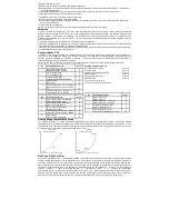
Speed-dependent (dynamic) period of the motor control
CV200 minimum speed
step (0-255) up to which the period duration = CV53 is set CV201 maximum speed
step (0-255) from which the period duration = CV202 is set CV202 maximum period
duration in 100µs steps
For the variable controller period, the period duration for internal speed steps smaller than CV200 is set to the value from
CV53. Up to the speed step according to CV201, the period duration is linearly changed up to the value in CV202. For all
driving levels above CV201, the period is set to the value of CV202.
The engine control can be adapted to the locomotive via the CVs 53 to 58 and 200 to 202.
In order for the decoder to use the dynamic period duration, it must be switched on via the CV51 bit 2.
Instructions for changing the controller parameters P, I, D:
Before changing the controller parameters, make sure that
1. The transmission is smooth running
2. The collector of the motor is not smeared
3. No capacitors from motor to chassis (ground) are present
Once these three points have been processed, you can start with the settings according to the following pattern.
) Enable PID control, bit 1 in CV51 = 0
) Set PID control offset CV57 = 0
) With the factory setting of the decoder CV2, 5 and 6 (min, max and medium speed) preset the motor control via CV54, 55
and 56.


