CX2936
I
NSTALLATION
10
4
Installation
4.1
General installation information
The valid national regulations for electronic installations
(e.g. VDE regulations) must be observed.
The connecting cables must be available and laid.
Only operate the device at the correct operating voltage.
If possible, disconnect the load and operating circuits.
In the case of installation on metal surfaces or in direct proximity to metals,
the range as well as the communication between product and connected
locking units may be influenced negatively.
Avoid direct exposure to strong electromagnetic fields
Do not paint over, paste on or cover the wireless switch module.
4.2
Installation
Specify the mounting position. Ensure that the surface is smooth, dry and firm
enough. Do not place the units close to each other to avoid radio interfer-
ences.
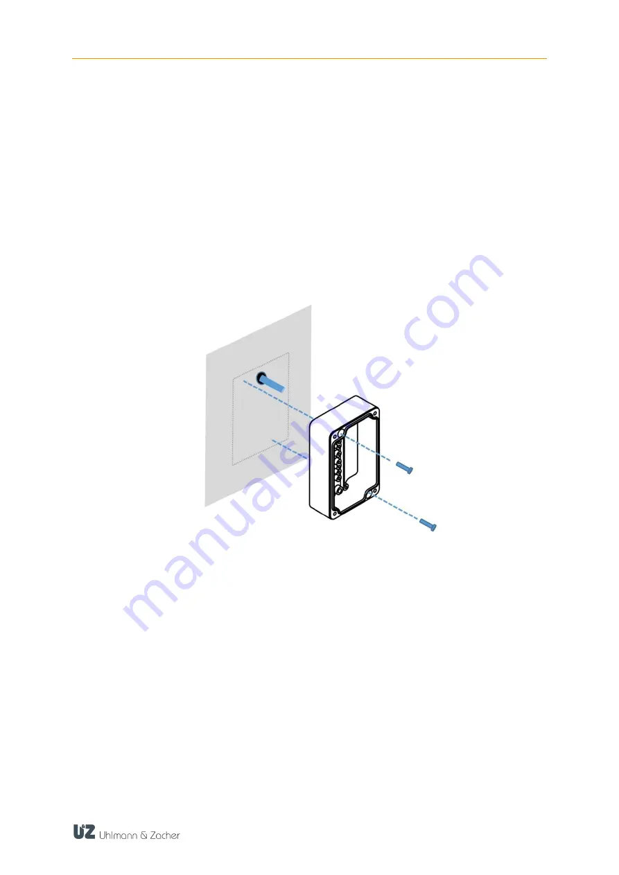
Mark the fastening points through the bottom of the housing
(No. 9 in layout diagram).
If required, drill mounting holes into the mounting surface.
Insert the connection cables through the opening on the bottom into the
housing and cut and strip to a suitable length.
Hand-tighten the lower part of the device at the intended location using suit-
able flat-head screws. Installation material is not included in the scope of de-
livery. In case of cable feeding from the side, use additional fitting rubber or
plastic spacers. Ensure that the cable is not pinched.
Wire cables according to the respective pin assignment specified in the next
chapter. The two 8-pin connection blocks can be removed for easier installa-
tion.
Perform commissioning (see the "Commissioning" chapter).
Put on the housing cover and screw it tight.


