

UHP-200 HIGH-THROUGHPUT SATELLITE ROUTER
GENERAL DESCRIPTION AND INSTALLATION GUIDE, v3.2
© UHP NETWORKS INC 2015
17
www.uhp.net
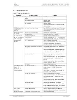
Symptoms
Possible reasons
Actions
LOCK indicator is
lighting, but TX
indicator is off)
allowed by Hub (only for TDM/TDMA
terminal)
Station is not
transmitting
(Reception is normal:
LOCK indicator is
lighting, TX indicator
is blinking, but
transmission is not
received by
Hub/opposite station)
IF Tx cable failure
Check Tx cable and make sure that its connectors
are properly connected to the BUC and the router.
BUC is not powered
Check if BUC power is switched on
Disconnect Tx IF cable from BUC and make sure that
24 VDC is available on the connector.
BUC failure
Replace the BUC on the spare one
Other symptoms
Other reasons
Contact your dealer or service center
In many cases, reinstalling system software allows to restore a satellite router functionality, which may need reset
to the factory default configuration.
If the recovery of software cannot be implemented successfully, or if this operation does not eliminate the defect,
it is necessary to illuminate the faulty device and replace it by new device.
4.1
Resetting to default settings
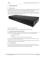
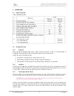
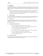
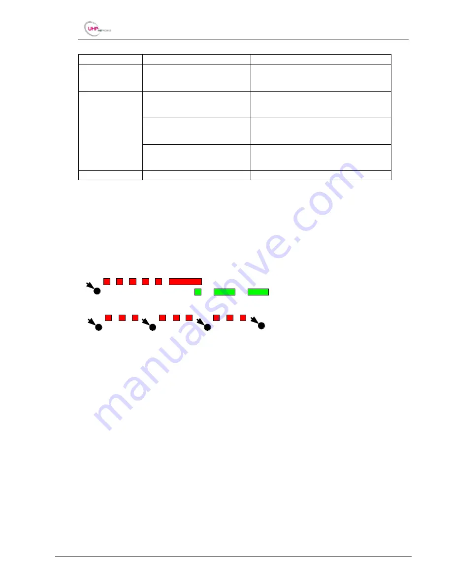
To reset user settings you can make use of a special restart procedure. Press RESET button four times with 2
seconds intervals.
Figure 8 Router resetting to default procedure
Successful reset will be evidenced by fast and simultaneously flashing indictors ERROR and SYSTEM.
By default, UHP-200 router is provided with IP-address 192.168.222.222 with mask 255.255.255.248 (/29).
Respectively, the computer should be provided with an address, e.g. 192.168.222.217 with the same mask.
The default address is not shown in the route Table. And what is more, it disappears after the first saving of the
configuration. Thus the first thing to do, with the Telnet access, is to set a new IP-address (it may be similar to the
default address when required), exit the session, and connect to the new address and only then save the
configuration.
After the first saving of the configuration the ERROR and SYSTEM indicators stop flashing simultaneously.
Push reset
Push reset
Push reset
Push reset
Factory default reset
Push reset
Normal reset


