MD40
PRODUCT INSTRUCTION MANUAL
MD40
Page 37 of 56
Author: N.Carapiet | Revision: 1.1
2.4.4 Oper
a
tion
Important
Safety Information!
Exercise extreme caution when using compressed air and ensure only competent persons are
responsible for connecting the pneumatic and electrical circuit.
Keep hands clear of the mechanism during operation.
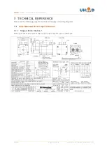
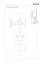
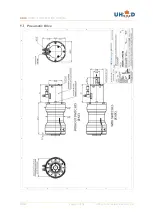
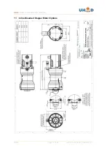
The pneumatic rotary actuator used is a vane type that requires air pressure on one port or the
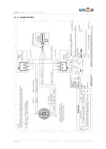
other to force it to sweep through its set stroke. See diagram in the Technical Reference section
which shows a typical pneumatic circuit for providing air control to the actuator.
Air is switched in this circuit using a five port, solenoid activated spool valve, with a spring return.
The valve has two ports on one side and three on the opposite side. The centre port of three is
connected to a regulated, clean dry air supply set between 3 & 5 bar. The two opposite ports
should be connected to the fittings mounted on the rotary actuator flow controllers. Use 4mm (or
1/8”) OD pneumatic compatible, nylon tube. Ensure the tube is pushed firmly into the fitting.
Consult any leading pneumatic company for the components required to control the actuator.
2.4.5 Flow Controller Settings
If the flow controllers are not set correctly, then the load may be subject to high acceleration.
There is a risk that the load inertia may de-couple the magnets in the rotary feedthrough. In order
to avoid this, it is critical that the flow and pressure settings to the actuator are correct.
The pressure is controlled through the system pressure controller which should be set to 4 Bar for
initial trials.
The flow controllers supplied will restrict air exhausting from a pneumatic actuator port, but ensure
high flow for the inlet. (The flow controllers are supplied fully closed.) Release the lock nut and
rotate the screw anti-clockwise to increase the mechanism movement speed. Cycle a few times
before resetting.

