background image


UI Robot Technology Co. Ltd. 

M4220161122CN 

Page 61 


UI 

– SR Series User Manual


Gently shake the 

cable by hand to 

confirm whether 

there is 

disconnection 

External cable(including 

cable units of robot) 


√ 

√ 

Press each arm by 

hand in power-on 

state to confirm 

whether there is 

rocking 

Joints 


√ 

Check for abnormal 
sound and vibration 

Overall 

√ 

√ 

√ 

√ 

√ 

use gauge to 

measure 

repeatability 

Overall 


√ 


2.3   Grease Filling 

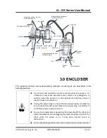
Ball screw splines require periodic greasing. Be sure to use the specified grease.  


★ 

Please pay attention to avoid grease running out. If the grease is used 
up, the sliding part may cause scratches and the like, and not only can 
it not perform well, but the repair will take a lot of time and expense.  


Part  

Period 

Grease 

Method of grease filling 

The  third 
joint 

Ball 
screw 
splines 
shaft 

After  moving  50km 

for  the  first  time,  
then  move  each 
100km 

LUBE 

6.0 ball screw splines unit 


★ 

Once grease into eyes, mouth or adhension to skin, please carry out 
the following treatment.  

Into eyes: Please wash your eyes thoroughly with water, and then go 

to see a doctor. 

Into  mouth:  Do  not  force  vomiting  when  swallowing,  should 

immediately go to see a doctor  
When  mouth  is  greased,  please  rinse  your  mouth 
thoroughly with water. 

Adhenring to the skin: please wash with water and soap.  

2.4   Fastening of hexagon socket head bolts 

Use  the  hexagon  socket  head  bolts  (hereinafter  simply  “bolts”  for  short)  where  mechanical 
strength is required. When assembling, tighten the bolts follow the tightening torques shown 

Summary of Contents for UI-SR Series

Page 1: ...User Manual UI SR Series SCARA Robot V1 2...

Page 2: ...QUALITY PERFORMANCE MERCHANTABILITY OR FITNESS FOR PURPOSE UIROBOT disclaims all liability arising from this information and its use Use of UIROBOT products in life support and or safety applications...

Page 3: ...23 3 5 Installation Procedure 24 3 6 Connecting the cables 25 3 7 Relocation and Storage 26 3 7 1 Precautions of relocation and storage 26 3 7 2 Relocation 26 4 0 Setting of end effectors 27 5 0 Moti...

Page 4: ...Encloser 65 3 3 Under Encloser 66 3 4 Interface Board 66 4 0 Cable 68 4 1 Replacement of Cable Unit 68 4 2 Wiring Table 72 5 0 Disassembly and Installation of joints 76 5 1 The First Joint 77 5 2 The...

Page 5: ...Ltd M4220161122CN Page 5 UI SR Series User Manual BASIC TECHNIC This volume contains information for setup and operation of UI SR series robots Please read this volume thoroughly before setting up an...

Page 6: ...ety considerations are indicated throughout the manual by the following symbols Be sure to read the descriptions shown with each symbol Warning This symbol indicates that a danger of possible serious...

Page 7: ...alled for the robot system The following items are safety precautions for design personnel Warning The robot and controller must be used within the environmental conditions described in their respecti...

Page 8: ...robot moves unexpectedly Warning To shut off power to the robot system pull out the power plug from the power source Be sure to connect the AC power cable to a power receptacle Do not connect it direc...

Page 9: ...the robot is not moving Do not press the emergency stop switch unnecessarily while the robot is operating Do not turn off the controller when the robot is running If user stop the robot by turning off...

Page 10: ...ower When the system is placed in emergency mode push the arm or joint by hand gently as shown below Joint 1 Push the arm by hand Joint 2 Push the arm by hand Joint 3 Rotate the shaft by hand Joint 4...

Page 11: ...abels Do not tear damage or remove the labels Labels NOTE A Before loosening the base mounting screws hold the arm and secure it tightly with a band to prevent hands or fingers from being caught in th...

Page 12: ...SR series robot are as follows No Electric Cabinet All joint motors use drive control integrated machine which can result in simple wiring Large Capacity It supports the U axis allowable moment up to...

Page 13: ...13 UI SR Series User Manual 2 2 Model Number UI SCR 4 150 L L 1kg H 3kg 120 120mm 150 150mm 170 170mm 200 200mm 4 400mm 6 600mm SCARA Robot UIRobot Payload Joint 3 Stroke Arm Length For details on th...

Page 14: ...rming any work with the power ON is extremely hazardous and it may result in electric shock and or inproper function of the robot system Make sure to turn OFF the controller power before the maintenan...

Page 15: ...UI Robot Technology Co Ltd M4220161122CN Page 15 UI SR Series User Manual UI SR 4150LS Standard Model Unit mm...

Page 16: ...ulse Joint 3 0 004 mm pulse Joint 4 0 045 deg pulse Shaft Diameter Installing 16mm Through Hole 9mm Mounting Hole 130 120mm 120 15mm 6 M8 Weight cables not included 13kg Standard Cycle 300mm 25mm Time...

Page 17: ...Max pulse range Joint 1 38250pulse Joint 2 38250 pulse Joint 3 25000 pulse Joint 4 4000 pulse 1 Conditions of robot during measurement as follows Operating conditions Under rated load 4 joints simulta...

Page 18: ...en swing angles of main arm and vice arm can achieve the best performance Assuming the ratio coefficient 2 1 C 1 and 2 are swing angles of main arm and vice arm respectively When 2 6 C 3 2 robot can a...

Page 19: ...When you need to change the setting of the robot model be sure to set the robot model properly Improper setting of the robot may result in abnormal or no operation of the robot and or cause safety pr...

Page 20: ...ts are not suitable for operation in harsh environments such as painting areas etc When using robot in inadequate environments that do not meet the above conditions please contact us 1 The ambient tem...

Page 21: ...ontal plate 50 Nm Max Horizontal reaction force 300 N Max Vertical reaction force 300 N The threaded holes required for mounting the robot base are M8 Use mounting bolts with specifications conforming...

Page 22: ...the space that they may reach Be sure to allow for the following extra spaces in addition to the space required for mounting the robot and peripheral equipment Space for teaching Space for maintenance...

Page 23: ...the delivery equipment the robot may fall Be careful not to get hands or fingers caught To carry the robot have two or more people to work on it and secure the robot to the delivery equipment or hold...

Page 24: ...s utilities other machines and equipment that may creat a trapping hazard or pinch points Caution Install the robot with two or more people Be careful not to get hands fingers or feet caught and or ha...

Page 25: ...system Be sure to connect the cables properly Do not allow unnecessary strain on the cables The unnecessary strain on the cables may result in damage to the cables disconnection and or contact failur...

Page 26: ...le hoisting is extremely hazardous and may result in fall of the robot When transporting the robot for a long distance secure it to the delivery equipment so that the robot can not fall If necessary p...

Page 27: ...switch is pressed I O outputs are configured at the factory so that they are automatically shut off by power disconnection the emergency stop switch or the safety features of the robot system Shaft At...

Page 28: ...ns in 5 1 to 5 2 to set the range 5 1 Motion Range Setting by Pulse Range Pulses are the basic unit of robot motion The motion range of the robot is controlled by the pulse range between the pulse low...

Page 29: ...defined as the positive and the clockwise pulse value is defined as the negative A Max Motion Range B Max Pulse Range SR 4150LS 135 deg 38250pulse 5 1 2 Max Pulse Range of Joint 2 The 0 pulse positio...

Page 30: ...than the 0 pulse position Joint 3 Stroke Lower Limit Pulse SR 4150LS 150mm 25000 pulse 5 1 4 Max Pulse Range of Joint 4 The 0 pulse position of Joint 4 is the position where the flat near the end of t...

Page 31: ...threaded holes in the positions corresponding to the angle for the mechanical stop settings Install the bolts in the holes corresponding to the angle that you want to set Joint 3 can be set to any len...

Page 32: ...orresponding to the angle that you want to set Install the bolts for the mechanical stop to the following position Mechanical Stops of Joint 1 Views from the bottom of Arm 1 Setting Value SR 4150L Set...

Page 33: ...UI Robot Technology Co Ltd M4220161122CN Page 33 UI SR Series User Manual SPECIFIC OPERATION Steps and precautions during using UI SR series robots...

Page 34: ...1 1 Installation of SCARA Software Copy the installation file SCARASetup exe to your computer s hard drive and double click the file to install The computer screen will appear the installation interfa...

Page 35: ...o modify the installation directory click the BROWSE button if not just click the INSTALL button It starts to install the software waiting for the installation to be completed After the installation a...

Page 36: ...Include The folder includes head file to call SDK dynamic library LIB The folder includes files required for SDK static calling ExampleCode The folder includes source codes to call SDK dynamic library...

Page 37: ...ual 1 2 Uninstall of SCARA Software Double click the uninst exe file in the installation directory to uninstall the software as shown in the following figure Click the YES button all the files in the...

Page 38: ...program or to easily creat new program 2 1 Start Program After the success of SCARA software SCARA installation double click the SCARA icon then enter the login screen There are 3 kinds of mode for us...

Page 39: ...with robot in the serial numbers drop down menu Click the open serial port button to establish the communication then enter main menu interface Network connection Import IP address and correct passwor...

Page 40: ...the feedback information from robot after the execution of instructions the left middle lower part of the screen shows the current running state of robot on the right side of the screen are function...

Page 41: ...st in robot Operation description select one program within the program list then Click simulation button the left 3D demonstration box will display the simulation of programs users programming Click...

Page 42: ...erface which contains six parts program install move I O camera mode and log 2 5 1 Program Click program button enter programming interface and can achieve functions as new program loading program fro...

Page 43: ...n move up the selected program Select one program from program editing window click down button move down the selected program Select one program from program editing window click copy button copy the...

Page 44: ...loop judge condition Execute code Condition of jumping out of the loop Double click while statement in program editing window automatically eject loop judge condition input interface Constants variab...

Page 45: ...nual Users can write statements throught loop judge condition input interface and assignment interface New variable Click new variable button in simple programmer interface enter new variable interfac...

Page 46: ...lt linear motion from user program generally have two groups of points each group has four values If user need more points can select one group of poits and click copy button on the right side to add...

Page 47: ...fast and easily pick up robot coordinate point through three kinds of ways that are dimensional coordinate axis rotation angle and manual control Long press teach button robot is in offline state user...

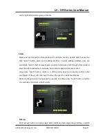
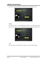
Page 48: ...t of 8 output ports according to actual needs Waiting Click waiting button in simple programmer interface enter programming waiting interface in which user can set up time waiting or IO input waiting...

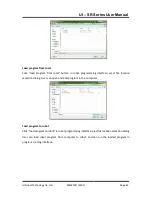
Page 49: ...obot programming interface eject file location selection dialog User can open and edit program in the computer Load program to robot Click load program tp robot in robot programming interface eject fi...

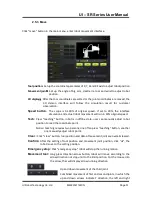
Page 50: ...select the program need to download click OK the program is downloaded to computer 2 5 2 Install Click install button in main menu enter robot tool center point setting interface When the center point...

Page 51: ...teaching button robot is in offline state user can manually adjust robot position to read the coordinate point Notice teaching requires two persons one often press teaching button another one manually...

Page 52: ...p and down 2 5 4 I O Click I O button in the main menu enter robot I O interface SCARA robot have 8 input ports 16 output ports In the interface user can query the state of each port 2 5 5 Camera Mode...

Page 53: ...record the feedback information after sending instructions to robot User can query the robot running state in real time 2 6 Robot Setting Click robot setting button in user interface to enter robot s...

Page 54: ...rd setting button enter login password setting interface In password setting interface the default original password is 1234 user can customize new password according to demand click OK to complete pa...

Page 55: ...etting interface user can change robot s intenal IP through setting of IP address subnet mask and default gateway for easy network communication 2 6 4 Time Setting Click time setting button enter robo...

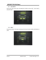
Page 56: ...Co Ltd UIROBOT SCARA Robot 2 7 Close Robot Click close robot button pop up a dialog box confirm to close robot click YES to close the robot 2 8 About Click about button the screen will pop up the cur...

Page 57: ...UI Robot Technology Co Ltd M4220161122CN Page 57 UI SR Series User Manual MAINTENANCE Steps and Precautions During Maintanance of UI SR series robots...

Page 58: ...tion training and maintenance Do not disassemble the parts that are not disclosed in this manual It is not recommended to carry out maintenance in a different way from the public Failure to perform pr...

Page 59: ...on and ensure safety it is required to reliably carry out inspection operation Check schedule and contents are as follows Please follow thw schedule to check 2 1 Check Schedule Check items are divided...

Page 60: ...end of clamps Setting bolts for robot joints Bolts around the shaft Confirm whether the connector is loose if so press in External side of robot connector board ect Cable unit Scar check car check re...

Page 61: ...but the repair will take a lot of time and expense Part Period Grease Method of grease filling The third joint Ball screw splines shaft After moving 50km for the first time then move each 100km LUBE 6...

Page 62: ...Locking Screw Tighten Torque Value M4 245 N cm 25 kgf cm M5 392 N cm 40 kgf cm As shown in the figure bolts arranged on the circumference are fixed in diagonal order Do not fasten the bolts once but f...

Page 63: ...he AC power cable to the power plug not directly to the factory power supply and so on Be sure to do replacement operation after powering off the robot and related equipments and unplugging the power...

Page 64: ...CARA Robot If the robot is turned on with a foreign matter entered it may lead to electric shock or malfunction which is very dangerous 3 1 User Board Disassembly of user board Upper encloser Under en...

Page 65: ...poor contact of cables malfunction of the system or electric shock Do not nip the cable or force it to bend during the installation of upper encloser otherwise it may casue damage disconnection or po...

Page 66: ...sassemble the clamp tip and then completely remove the under enclose When it not need to be disassembled please put the shaft down to lower limit position and then remove the under encloser for mainte...

Page 67: ...l Unscrew the fixing bolts of interface board then open the it Notice There is electrical interface on the inner side of interface board please slowly open the interface board from up to down to avoid...

Page 68: ...matter entered it may lead to electric shock or malfunction which is very dangerous Please connect the cable reliably In addition do not place heavy object on the cable do not extremely bend forcibly...

Page 69: ...heck the cable configuration and return to correct wiring while the cover is removed Please connect the cable reliably In addition do not place heavy object on the cable do not extremely bend forcibly...

Page 70: ...the interface board The color of each group of wires is red black white and blue respectively One group from the controller and the other from Bellows Disassemble the wiring you can remove the interfa...

Page 71: ...of wires in the connectors on the interface board and use a flat blade screwdriver to tighten the cables Notice 48V red 0V black CH white CL blue 4 Connect the network connector of interface board in...

Page 72: ...1500VA Power supply conditions of UI SR series robot power module Voltage 180 264VAC 47 63Hz or 254 370VDC Power 1500VA The UI SR series robot electrical terminal have two parts the top of the jib an...

Page 73: ...t of Power X3 Output Interface Pin Number Name Function 1 G0 Signal Ground 2 O1 Collector Open Drain Output of Signal 1 3 O2 Collector Open Drain Output of Signal 2 4 O3 Collector Open Drain Output of...

Page 74: ...llector Open Drain Output 14 PO14 Switch Value Output Signal Collector Open Drain Output 15 PO15 Switch Value Output Signal Collector Open Drain Output 16 PO16 Switch Value Output Signal Collector Ope...

Page 75: ...t X3 or X5 Figure 1 Figure 2 Wiring Diagram of Multi Function Interface X4 Pl1 PO9 Pl2 Pl3 Pl8 PO10 PO11 PO16 AGND AGND RST CH CL CANL CANH 24V Sensor X4 Multi Function Interface Sensor Sensor Sensor...

Page 76: ...on it may cause electric shock or malfunction Be careful not to apply excessive shock to the motor shaft during the replacement operation otherwise it may result in a short service life or damage of...

Page 77: ...s Maintenance components Integrated speed reducer of the first joint 1 UIM62H08A 8678X Grease NS2 Tools Hexagonal wrench double sided width is 2 5mm 1 For M3 screws Hexagonal wrench double sided width...

Page 78: ...l pedestal 3 Remove the bellows cover plate and unscrew the fixing screws of the arm under the bellows cover plate 4 Remove the outer ring screws at the cover plate of cylindrical pedestal and take ou...

Page 79: ...Co Ltd M4220160506CN 79 UI SR Series User Manual 5 Remove the inner ring screws at the cover plate of cylindrical pedestal to complete the disassembly of integrated speed reducer 9 M4 30 Hexagon Sock...

Page 80: ...ghten the fixing bolts 2 Place the assembled integrated speed reducer and the cover plate into the cylindrical pedestal align the screw holes and screw the corresponding screws 3 Place the arm on the...

Page 81: ...screws The free end of the bellows rotatably screw on the interface of the cylindrical pedestal 5 2 The Second Joint Name Quality Remarks Maintenance components Integrated speed reducer of the second...

Page 82: ...in 3 1 User Board 3 Remove the upper cover The details are described in 3 2 Upper Encloser 4 Unscrew the main arm fixing bolts M3 18 which is used to secure jib on the main arm After all the bolts uns...

Page 83: ...n consistency and take care not to cause damage 2 Place the jib on the main arm align screw holes and tighten all the bolts M3 18 During the installation please make the end surface of jib and that of...

Page 84: ...62C04A 5742 Tools Hexagonal wrench double sided width is 2mm 1 For M2 5 screws Hexagonal wrench double sided width is 2 5mm 1 For M3 screws Hexagonal wrench double sided width is 3mm 1 For M4 screws H...

Page 85: ...er beside the spline screw and loosen the fixing bolts M2 5 10 5 Unscrew the fixing bolts M4 10 of the Z shaft base This positon the Z shaft is secured at the top the jib 6 Unscrew the retainer ring a...

Page 86: ...on the base of Z shaft align screw holes tighten all the bolts M4 10 2 Place U2 belt on the synchronous wheel of integrated reducer and spline screw put the retaining ring on the belt tighten the reta...

Page 87: ...ttery plate on the 4th joint integrated reducer align the screw holes tighten with bolts M2 5 10 7 Install the upper enclose Details are described in 3 2 Upper Encloser 8 Install the user board Detail...

Page 88: ...ls Hexagonal wrench double sided width is 2mm 1 For M2 5 screws Hexagonal wrench double sided width is 2 5mm 1 For M3 screws Hexagonal wrench double sided width is 3mm 1 For M4 screws Hexagonal wrench...

Page 89: ...b 6 Unscrew the retainer ring M5 12 under the spline screw remove the Z shaft from the jib The base of Z shaft contains spline screw and the third joint integrated reducer Attention to extract the spl...

Page 90: ...the Z shaft base bolts M4 10 Notice Spline screw to be placed vertically in the spline hole so as not to affect the accuracy due to damage 5 Install the retaining ring M5 12 of spling screw 6 Secure t...

Page 91: ...tion between the origin stored in integrated machine and the origin stored in controller and it is unable to control correctly Therefore after the components replaced it is necessary to carry out the...

Page 92: ...Encloser 6 2 Replacement of Ball Screw Spline Unit Name Quality Remarks Maintenance components Ball spline screw 1 All types AC servo motor 100W Appropriate R13B010228 Tools Hexagonal wrench double s...

Page 93: ...7 0 The Fourth Joint 9 Unscrew the synchronization wheel fixing bolts M4 14 on the lower screw of the Z shaft base and remove the synchronous wheel 10 Unscrew the bolts M4 10 from the lower part of t...

Page 94: ...the accuracy due to screw damage 7 Fix the Z shaft base with bolts M4 10 Here the bolts tighten the Z shaft to the upper part of the jib 8 Install the retaining ring M5 x 12 to the lower part of splin...

Page 95: ...lems Charge Throw into fire Short circuit pole pole Disassembly Forced discharge Heating above 85 Anti loaded Compression deformation Welding direct to battery terminals To dispose of the batteries pl...

Page 96: ...lug the wiring of battery in the base cylinder remove the old battery and replace it with a new one 3 Remove the user board Details are described in 3 1 User Board 4 Remove the upper encloser Details...

Page 97: ...y Before operating the robot system make sure that there is no one inside the safety guard However the robot system can be operated in the teaching mode even if there is a person inside the security g...

Page 98: ...re StepEvi X enter its configuration interface 1 In the PTP interface for Motion Control click the Offline Enable button in the lower left corner so that the first joint integrated reducer is offline...

Page 99: ...0 5 Click the button to move the robot arm slowly to the position and then click the button the position is recorded as the origin of the first joint 8 3 The Origin Adjustment Procedure of the Second...

Page 100: ...verage value in the desired value of position and insert desired value of speed speed generally take 5000 5 Click the button to move the jib slowly to the position and then click the button the positi...

Page 101: ...ed value of speed speed generally take 5000 5 Click the button to move the screw lead slowly to the position and then click the button the position is recorded as the origin of the second joint From t...

Page 102: ...that the fourth joint integrated reducer is offline 2 Record the position value of the fourth joint integrated reducer when the third joint integrated reducer reach its origin position and the stepEVA...

Page 103: ...The Fourth Joint 100W 5 3 Synchronous Belt The Third Joint U1 Belt 5 4 The Fourth Joint U2 Belt 5 3 150mm 6 0 Battery Lithium Batteries for Replacement 7 0 User Board 3 1 Interface Board 3 4 Control...

Reviews: