第
94
页
M4220160506CN
UI Robot Technology Co. Ltd.
UIROBOT SCARA Robot
(
3
)
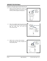
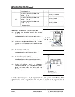
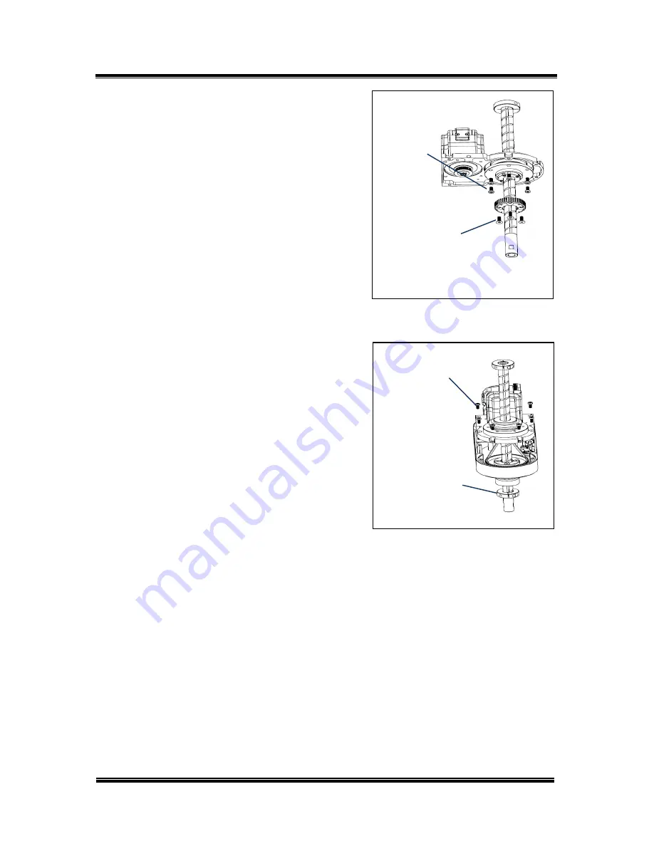
Place the screw nut in the lower part of the Z-
shaft base, align the holes, and fix it with bolts
(M4 × 10).
(
4
)
Place the synchronizer wheel at the lower part
of the Z-shaft base, align the holes, and fix with
the bolts (M4 × 14).
(
5
)
Install the U2 belt.
Details are described in “7.0 The Fourth Joint”.
(
6
)
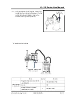
Attach the Z-shaft base to the jib. The Z-axis
base here contains the spline lead screw and
the third joint integrated reducer. Take care to
keep the screw vertical while placing the spline
screw, so as not to affect the accuracy due to screw damage.
(
7
)
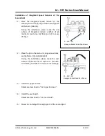
Fix the Z-shaft base with bolts (M4 × 10) .Here
the bolts tighten the Z-shaft to the upper part
of the jib.
(
8
)
Install the retaining ring (M5 x 12) to the lower
part of spline screw.
(
9
)
Install the lithium battery plate next to the
fourth joint integrated reducer and beside the
spline screw, tighten the bolts (M2.5 × 10).
(
10
)
Mounting clamp end and wiring / piping.
(
11
)
Install the upper enclose.
Details are described in “3.2 Upper Encloser”.
(
12
)
Install the user board.
Details are described in “3.1 User Board”.
(
13
)
Power on and adjust the origin point of the 4
th
joint.
Details are described in “8.0 Origin Adjustment”.
6 – M4
×
10
Hexagon
Socket-Head
Cap Screws
4 – M4
×
14
Flat-Head
Hexagon
Socket Screws
6 – M4
×
10
Hexagon
Socket-Head
Cap Screws
1– M5
×
12
Hexagonal
Socket

