Mounting the Router to the 10mm Table Inserts / Operating Instructions
28
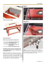
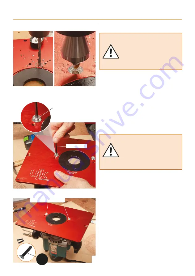
Fig 07-08
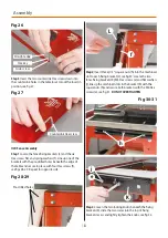
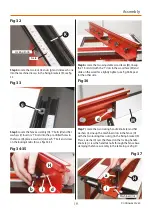
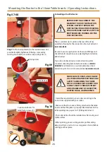
Step 7 Fix the insert plate (A) to the router (screws not
provided). Lightly tighten each fixing screw, evenly
working down each screw till secure, see figs 09-10.
Fig 09
Fig 10
Fixing screw
4mm Hex key
Countersunk holes for
table fixing screws (C)
C
BEFORE ROUTING CONNECT THE
MACHINE TO A DUST EXTRACTION
SYSTEM. ALWAYS TURN ON THE
DUST EXTRACTOR BEFORE STARTING
THE ROUTER AND ALWAYS STOP THE
ROUTER BEFORE TURNING OFF THE
DUST EXTRACTOR.
MAKE SURE TO READ, AND FOLLOW
ALL OPERATING INSTRUCTIONS AND
SAFETY GUIDELINES THAT CAME
WITH YOUR ROUTER FAILURE TO DO
SO MAY LEAD TO SERIOUS INJURY
AND/OR DAMAGE TO THE ROUTER,
ROUTER TABLE, OR WORKPIECE.
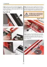
There is a 62mm dust outlet on the rear of the fence
assembly allowing for the connection of a dust extractor
(not included).
Be sure to use an appropriate size hose and fittings and
check that all connections are sealed tightly to minimize
airborne dust.
If you do not already own a dust extraction system,
consider contacting Axminster Tool Centre on 03332
406406 for information on our complete line of dust
extraction systems or visit our website at axminster.co.uk.
• Install the required bit in your router according to the
instructions supplied with your router.
• Make sure that the router is firmly attached to the table
insert and that the plate is properly fitted and level in the
table opening (see pages 16-17), fitting table insert.
• The router table should be installed on a flat, sturdy, and
stable surface.
• When jointing, groove cutting, and/or profile cutting
always perform a test cut on a scrap piece of wood before
cutting your final piece.
Connecting a Dust Extractor


