-7-
Pipe-work:
To avoid damage to the unit, to prevent failure and to ease maintenance, we recommend the following:
•
Pipe-work - fully support to avoid weight/forces acting upon the unit / connections.
•
The fitting of flexible couplings if the pipe work is subject to vibration.
•
The pipe work is completely flushed before attaching to exchanger. The exchanger acts as an
effective filter and will become blocked if pipe-work debris is allowed to enter the plate pack.
•
The fitting of suitable vents, isolation valves & drains. To allow servicing of the package without
complete system draining appropriate isolation valves should be fitted.
•
The fitting of non return valves where appropriate
•
The fitting of suitable sized pressure relief valves in the pipe work on both circuits (essential safety
requirement).
Sensors:
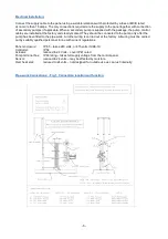
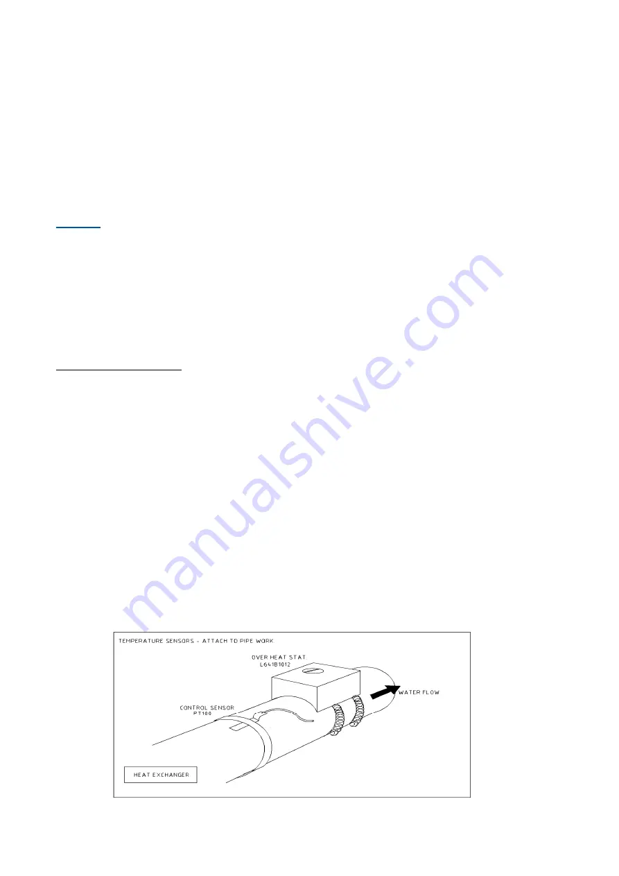
There are two temperature sensors – one for control and the other for over heat protection.
Both sensors are the strap on type, they both need to be attached tightly to the pipe work. If steel pipe work is
used, then for best results we recommend that a section of steel pipe is replaced by copper, and the sensors
attached to this section of copper. Both sensors should be connected to the secondary flow pipe work going to
the services (flow from F3 connection). The control sensor needs to be attached to the pipe between 250 to
500 mm away from the exchanger, and the over heat located just after the control sensor. Route and clip the
wires as necessary – do not attach any wires near, or onto the tie bolts, or along the length of the top
horizontal frame bar of the heat exchanger.
Temperature sensors wires
Wires to both the sensor and the over heat stat can be extended - they are not any special wires - 2 core flex
for the sensor and 3 core for the over heat stat.
You shall loose accuracy of the temperature readings (by as much as 2 deg C), but it shall be consistent for all
readings recorded by the panel. This is due to additional resistance that the extended wires shall impose.
Remove the wires directly from the panel - add a junction box and then run you extended wires from the
respective junction boxes to then connect into the panel. If you cut the old wires, you shall have to add 2
junction boxes to increase the length and this shall add even more resistance - therefore, the use of one box is
the better way to do things.
Longer wires increase the resistance by 0.1 ohms per metre, hence the accuracy of the controller is reduced
(5 metres of wires = +/- 2 C accuracy)
The PT100 gives a resistance of 38 ohms
The wire = 0.1 ohms per metre
The controller compares the resistance between an internal resistor and the sensor loop, then subtracts the
one resistance from the other to come up with a reading. Therefore, if the wires are increased in length, this
comparison of resistances is different from the “expected” – hence a slightly different reading is recorded


