


19
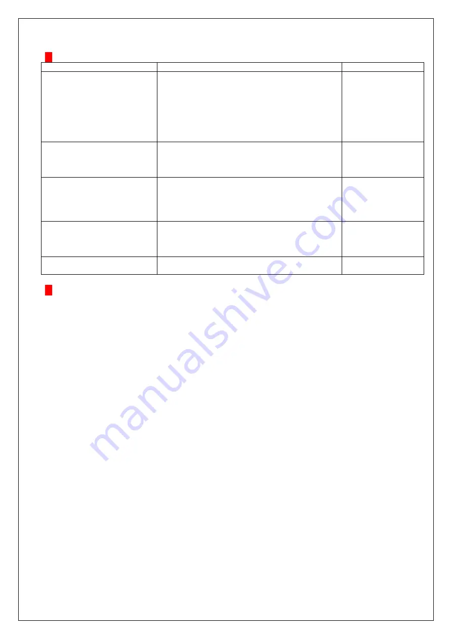
Fault diagnosis schedule
Fault
Cause
Action
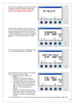
The burner has stopped.
Fuel fault
on display.
1. The pellet storage is empty.
2. Air pocket has been created in the inlet of the
feed auger.
3. The auger has been blocked by waste.
4. Stop in tipping chute.
1. Fill with pellets.
2. Shake the storage
so that pellets fall
down.
3. Knock hard on the
conveyor.
4. Too big start dose.
Decrease start dose.
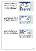
The burner stops even though it
ignites.
1. Too heavy feeding at operation level.
2. Flame guard dirty or broken.
1. Adjustment of fuel
amount.
2. Clean or change
flame guard.
The burner does not ignite.
Ignition fault on the display.
1. Wrong start dose.
2. Broken ignition element.
3. Stop in tipping chute.
1. Change start dose.
2. Change ignition
element.
3. Clean tipping
chute.
The burner stops now and then
without visible reason.
1. Incorrectly adjusted burner.
2. Too big or heavy under pressure in the chimney.
3. Error in the fuel feeding.
1. Adjust the burner.
2. Mount draft limiter.
3. Clean feed auger
from chips.
Overheating on display.
Too bad draft in the boiler.
Sweep the boiler.
Data
and Service information
Safety regulations
The product is CE-marked which means that it fulfills all prescribed requirements that exist to put the product
into work within the EU. ULMA AB disclaims all responsibility that could occur at misuse or wrong use of the
Ulma3000TCA burner.
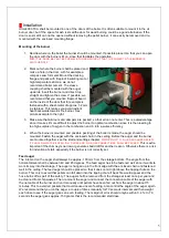
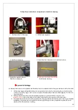
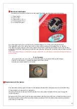
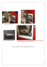
Change of ignition element
1. Loosen all 3 cables to the burner.
2. Demount the burner cover by loosing the 4 screws and then carefully pull the cover backwards.
3. Loosen the quick-action hooks that hold the outer pipe towards the back cover. Carefully separate the
burner.
4. Loosen the screw that holds the ignition element and pull out the element from its position.
5. Re-mount in reverse order.
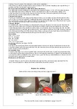
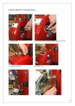
Change of flame guard
1. Loosen all 3 cables to the burner.
2. Demount the burner cover by loosening the 4 screws and then carefully pull the cover backwards.
3. Loosen the connection cables on the control system and pull out the giver from its hole to the left of the
fan.
4. Push in the new giver in the holder 25 mm and fasten the nut. Connect the connections to the control
system and remount the burner cover in reverse way.