background image


LAS 260.1 

– Date 07/2023 

Potential malfunctions 

Page 41


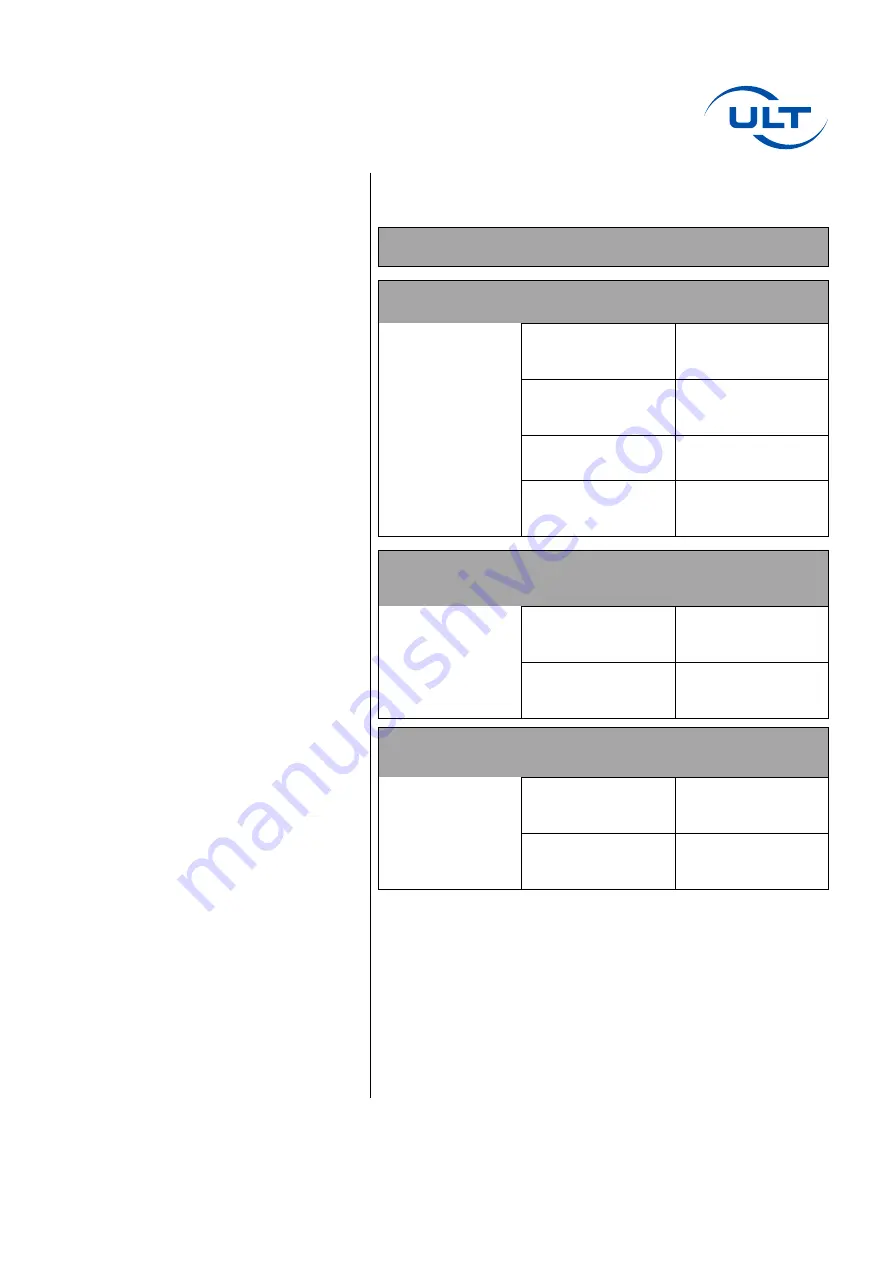
Potential malfunctions 


Error 

Possible cause 

Remedy 


Fan not starting up


No power supply to 
the unit 

Check the power 
supply at the mains 
outlet. 


Fault in the unit/control 
electronics 

Have repairs carried 
out by a specialist 
(specialist dealer) 


Defective unit fuse 

Replace the fuse 


Signal for remote 
ON/OFF not present 

Check the interface 
M12 and the bridge 
switch 


Inadequate suction 
and filter 
performance 


Air passage 
obstructed 

Check the suction 
path and the outlet air 
guidance 


Filters are saturated 

Check the filter 
saturation indicator, 
replace the filter(s) 


Poor filtration 


Filters are saturated 

Check the filter 
saturation indicator, 
replace the filter(s) 


Filters are not in the 
correct position 

Check the seating of 
the filters 


Summary of Contents for LAS260.1

Page 1: ...Valid for variant 1 00192 LAS 260 1 MD 20 FK Operating Instructions LAS260 1 Extraction and Filtration Unit Date 07 2023...

Page 2: ...ULT AG Am G pelteich 1 02708 L bau Germany Phone 49 3585 4128 0 Fax 49 3585 4128 11...

Page 3: ...information 13 Technical Overview 14 Technical Illustration 15 Technical Data 16 Function and operation 18 Device variant and application 19 Transport and storage 20 Installation 20 Installation and...

Page 4: ...installation 34 Optional outlet nozzle 37 LED status messages 38 Status white 38 Status green 38 Status orange 39 Status red 40 Potential malfunctions 41 Replacement and wear parts 42 Filter list 43 S...

Page 5: ...d the corresponding documentation at any time without prior notice This does not result in an obligation to update previous documents Intended use The intended use is defined in the following section...

Page 6: ...during all other work on the LAS 260 1 the operating company is responsible for the following in all cases Safety of all persons involved Safety of the device and all other parts of the equipment Env...

Page 7: ...act explosive concentrations of gases vapors or dusts DANGER Health hazard Do not use the equipment to extract substances that are carcinogenic mutagenic or toxic for reproduction and or toxic gases v...

Page 8: ...ons before starting work and will confirm with their signature that they have understood them WARNING Make sure that you never use any products that are damaged Read these operating instructions caref...

Page 9: ...that are relevant in terms of technical safety To avoid the risk of fire and explosion the system must never be used to extract e g hot glowing smoldering parts glowing ashes shavings filings or smol...

Page 10: ...l and mechanical engineering Here a skilled person is someone who based on their professional training knowledge and experience as well as their knowledge of the relevant standards and regulations is...

Page 11: ...or endanger the safety of personnel the unit or the working area and its surroundings The operator is obliged to immediately report any safety related changes occurring on the unit Observe all attach...

Page 12: ...that can only be removed with tools The system corresponds to protection class I in accordance with EN 60335 RESIDUAL RISK Severe injuries due to electric shock can be caused if a fixed securely moun...

Page 13: ...EE Directive 2012 19 EU and of the German Electrical and Electronic Equipment Act ElektroG ULT AG is licensed in Germany by Stiftung Elektro Altger te Register EAR as a manufacturer under the WEEE reg...

Page 14: ...Page 14 Technical Overview LAS 260 1 Date 07 2023 Technical Overview Overall system 1 Intake nozzle 2 Filter chamber door 3 Clean gas outlet 4 Casters 5 Connections on the rear 6 Front operating panel...

Page 15: ...LAS 260 1 Date 07 2023 Technical Illustration Page 15 Technical Illustration Dimensions Dimensions mm A 440 B 960 C 435 D 495 E 80 F 50 G 255 H 445 I 100...

Page 16: ...condensing Air intake 1x pipe nozzle DN80 Air outlet Outlet grille or outlet nozzle DN100 on rear of unit Performance data MD 20 Max volumetric flow rate 360 m h Max vacuum 9 500 Pa Rated volumetric f...

Page 17: ...Switchover medium pressure high pressure operation Universal LED status ring for particulate filter saturation and device status Outlet grille air outlet flange collar DN100 ecoflow CS for maintainin...

Page 18: ...be collected and sucked out directly at the point of creation The contaminated air is guided through the filters in the LAS 260 1 and purified The purified air passes through an integrated muffler an...

Page 19: ...ed directly at the point where they are generated Filter FK Pre filter Particulate filter cassette F9 Raw gas intake Pleated filter F9 Filter class ISO ePM1 80 in acc with ISO 16890 Main filter Combin...

Page 20: ...on about proper disposal The Extraction Unit should be set up in the place intended for it It should be on a level floor and standing upright with horizontal surfaces properly leveled Apply the brakes...

Page 21: ...tion element The unit must only be moved with the casters on level surfaces If it is moved with the casters on an inclined surface there is a risk that control over the unit could be lost resulting in...

Page 22: ...Use of other mains cables may result in damage to the device M12 interface NOTICE As standard the M12 interface provides the following functions status message filter warning filter full and remote O...

Page 23: ...ly cable DANGER Never operate the unit without a filter Operation Switch on the LAS 260 1 via the ON OFF switch on the front of the unit Before taking the unit into operation check that the suction co...

Page 24: ...check whether the filter is correctly seated Afterwards you can carry on working normally with individual suction power settings LED status ring The LED status ring indicates the status of the unit an...

Page 25: ...e solely via the operating controls on the front and rear of the machine Prerequisite for standard operating mode Switch S2 in position I The suction power can be individually adjusted via the potenti...

Page 26: ...points during ongoing operation e g open or closed extraction arms are automatically compensated for by increasing or reducing the blower speed Characteristic curves and operating modes Characteristic...

Page 27: ...freely adjusted up to the maximum rotational speed S3 switch is in the position I o ecoflow CS in medium pressure operation ON Control range of the potentiometer in position I Medium pressure operati...

Page 28: ...the LAS 260 1 S2 switch is in the position 0 The operator can still adjust the suction power by hand on the potentiometer and switch on the ecoflow CS via the S3 switch see section ecoflow CS If no hi...

Page 29: ...the collection device Yearly main inspection By arrangement with ULT AG the main inspection can be performed by ULT Service By arrangement with ULT AG further measures that go beyond the scope of the...

Page 30: ...lutants impurities present the activated carbon will become saturated The time until saturation occurs needs to be determined and the filter should then be regularly replaced whenever this time limit...

Page 31: ...storage filter elements used in the unit are not suitable for cleaning with compressed air If the filters are blown out with compressed air this will destroy the filter membrane and release any dusts...

Page 32: ...Page 32 Maintenance and servicing LAS 260 1 Date 07 2023 2 Open the door catch on the left hand side of the unit 3 Open the filter chamber door...

Page 33: ...servicing Page 33 4 Take out the saturated filter and place it in a suitable disposal container that can be sealed airtight CAUTION When taking out the filter support the frame from underneath to prev...

Page 34: ...aturated main filter to the top holding it by the grip tabs Then pull it out to the front and place it in a suitable disposal container that can be sealed airtight Filter installation 6 Before install...

Page 35: ...7 Insert the new main filter cassette Make sure that the seal on the underside of the filter cassette is not damaged in the process 8 Insert the new pre filter cassette Make sure that the seal on the...

Page 36: ...f it is damaged or incomplete NOTICE The owner of the waste which in this context is normally whoever generates the waste is responsible for proper recycling or disposal of the waste The operator is r...

Page 37: ...ed via the outlet nozzle into an air outlet system Tools required 2 5 mm hexagon socket screw key Remove the eight M4x12 screws on the rear of the unit and take off the outlet grille Rotate the air ou...

Page 38: ...a signal from a higher level machine or from an optionally available pedal switch This message is only output if the S2 switch is in the 0 position Status green NOTICE No errors Continuously on The u...

Page 39: ...utside of the unit specifications Connect the suction section Reduce the diameter of the suction section Switch the control mode from high pressure operation to medium pressure operation Check the suc...

Page 40: ...ed in the unit The intake is possibly blocked The set volumetric flow rate is too low The blower is possibly defective Insert a particulate filter Check the particulate filter for damage and correct s...

Page 41: ...er Defective unit fuse Replace the fuse Signal for remote ON OFF not present Check the interface M12 and the bridge switch Inadequate suction and filter performance Air passage obstructed Check the su...

Page 42: ...p rocker switch 6 03859 Protective cap M12 black 6 09330 Caster with wheel lock 6 00027 Outlet air adapter 3 01273 Wear parts Vacuum generator 3 00302 When placing an order please always quote the ite...

Page 43: ...filter cassette F9 4 00107 Main filter Combined filter cassette H14A10 4 00109 NOTICE Only use genuine filters from ULT AG This is the only way to ensure that the stated filter performance can be achi...

Page 44: ...S 260 1 Date 07 2023 Service The following services are available Supply of accessories Supply of spare parts Supply of replacement filters Ongoing maintenance Performance of any necessary repairs Dis...

Page 45: ......

Page 46: ......

Page 47: ...E D C B A Approved on Created by 1 POT_FREE_CONN K1 EFA 2 6 A OUT Common contact for 2 3 4 X3 K1 KF1 K1 EFA 2 1 A 2 POT_FREE_1 K1 EFA 2 6 B OUT Status operation 3 POT_FREE_2 K1 EFA 2 6 B OUT Status fi...

Page 48: ......

Page 49: ...Rating Status Description 30 VDC 100 mA Open Closed Machine operating Machine out of operating Filter 80 depleted Filter OK Filter 100 depleted Filter OK High Low Status operation 1 Status filter 1 R...

Page 50: ......

Reviews: