background image

 76


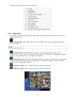
64-Split Screen Mode:

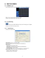
 Click on 64-SPLIT button and 64-split screens will display. 


 Zoom Mode:

 Click on Zoom button. Then, the setup screen will disappear and only the video image will be zoomed 

(scaled to fit the screen). To cancel, please press the right mouse button. 


  E Map: load and close E Map image program.


Mouse Double Click:

 If user does double click of the mouse on a split screen, it will turn to full screen mode. Double click 

the mouse to back to the previous watch mode. 


8.3.3 Multi 

Screen 

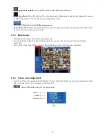
 CMS supports multi remote site connections simultaneously. 

 Server Drag & Drop: Drag & Drop Remote Site of site tree to any screen. Then all cameras of the site will display 

sequentially. 

 Camera Drag & Drop: Drag & Drop a camera of Remote Site to any screen. Then the camera will display. 


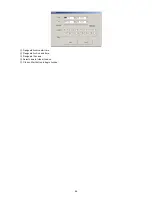
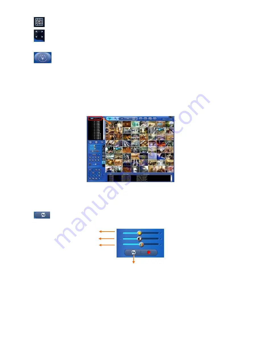
8.3.4  Screen Color Adjustment 

 Adjust color of the screen using three bars (Brightness / Contrast / Saturation). Selecting a channel and dragging the bar(s) 

with a connected mouse. Color will change in about 7 seconds. 


  Click on UNDO button to return to the original colors. 


Saturation

Brightness 

Undo 

Contrast

Summary of Contents for M4229KQCT

Page 1: ...Standalone Digital Video Recorder Premium DVR 4 8 16 Channel Models User s Manual MADE IN KOREA M4229KQCT This document contains preliminary information and is subject to change without notice KQ3...

Page 2: ...he equipment The equipment complies with the requirement of FCC CFR 47 PART 15 SUBPART B Class A Explanation of Graphical Symbols Warnings Installation and servicing should be performed only by qualif...

Page 3: ...water or in contact with water 6 Accessories Do not place this equipment on an unstable cart stand or table The equipment may fall causing serious injury to a child or adult and serious damage to the...

Page 4: ...s to determine that the equipment is in proper operating condition 16 Field Installation This installation should be made by a qualified service person and should conform to all local codes 17 Correct...

Page 5: ...e List of Configuration DVR Set A and C Type 4CH 8CH 16CH B D E and F Type 4CH 8CH 16CH CD CMS Software Manual Remote Controller Manual Screws HDD Brackets Data Cable Power Cable Except E and F Type M...

Page 6: ...ormation Status Setup Default HDD format HDD format is done by SETUP SYSTEM Admin Storage Format If there are more than two HDDs each must be formatted separately When the format is completed DVR will...

Page 7: ...32 4 2 4 System Log 34 4 2 5 Exit 34 4 2 6 Shutdown 35 4 3 DISPLAY 35 4 3 1 OSD 35 4 3 2 Main Monitor 36 4 3 3 Spot Monitor 36 4 3 4 Spot Monitor Control on Display Mode 37 4 3 5 Multi Spot C and D Ty...

Page 8: ...4 Connection 99 12 1 5 PTZ Control 99 12 1 6 Disconnection 100 12 1 7 Uninstall 101 12 2 Android Phone 102 12 2 1 System Requirements 102 12 2 2 Installation 102 12 2 3 Site Registration 103 12 2 4 C...

Page 9: ...Supply Adapter DC 12V 5A and Power Supply Cable D Type Power Supply Adapter DC 12V 6 67A and Power Supply Cable E and F Type Power Supply Cable Remote Control With 2 AAA batteries Installation CD CMS...

Page 10: ...10 B Type 4 8 16 channel Series DVR...

Page 11: ...11 C Type 4 8 16 channel Series DVR...

Page 12: ...12 D Type 4 8 16 channel Series DVR...

Page 13: ...13 E Type 8 16 channel Series DVR...

Page 14: ...14 F Type 4 channel Series HD SDI DVR...

Page 15: ...ed onto correct SATA port Refer to below table to mount a hard disk and DVD RW A and C Type 4 8 16 CH DVR Storage SATA 1 2 Port SATA 3 Port HDD DVD RW 1 2 3 1 1 HDD DVD RW 2 1 HDD HDD DVD RW B Type 4...

Page 16: ...tion Addition Moving Replacement User should start HDD initialization including formatting Otherwise DVR won t recognize the hard disk and may begin to function abnormally Please follow the below proc...

Page 17: ...e connected properly not oppositely NOTE Only B D and E Type model support LOOP OUT connection and F Type supports HD SDI LOOP OUT connection 2 2 2 Monitor Connections Video Out VGA and Spot Use with...

Page 18: ...2 2 9 RS 232 Connections This port is not in use for users Do not connect any devices through this port 2 2 10 Factory Reset Switch Reset the switch to restore all setup values of menus to factory de...

Page 19: ...the monitor to 75 ohms to prevent abnormally bright or collapsed images If wish to connect another device e g a recorder to the back of the monitor please set the impedance switch on the rear side of...

Page 20: ...udio on off Viewing Playback Select audio channel Press AUDIO key and then channel key ESC MENU Enter the Main Menu Setup mode REW Fast backward playback changes up to x128 with each press Zoom Out on...

Page 21: ...then channel key ESC MENU Enter the Main Menu Setup mode REW Fast backward playback changes up to x128 with each press Zoom Out on PTZ mode BACKWARD Frame backward playback Zoom In on PTZ mode PLAY P...

Page 22: ...Select Camera No 10 16 press key and use 1 6 key B D E and F Type Below shows how to select camera channel for 4 8 16channel DVR Below shows how to select camera channel for 4 channel DVR Select Came...

Page 23: ...ID button 3 5 Using a Mouse Mouse provides an easier access to adjustment Refer to below for proper use Left mouse button functions the same as Enter key on the front panel of DVR Right mouse button d...

Page 24: ...recording Event recording mode Alarm In Motion 4 CMS access indication No of accesses up to 4 In recording In channel sequencing PTZ registration PTZ mode Lock Remote Controller Setup in HDD Overwrit...

Page 25: ...n successfully following screen will appear Recording continues during setup Main menu consists of 5 sub menus SYSTEM DISPLAY DEVICES RECORD LINK There is no factory default in the case of passwords T...

Page 26: ...l System ID Control DVRs by one remote controller by setting DVR IDs Please click direction keys on the right hand side of the System ID frame to set the ID of DVR Take any whole number between 1 and...

Page 27: ...When user complete Status data input please click Version and the following screen will appear Version Upgrade User may upgrade DVR software Please follow the Upgrade procedure below Plug USB memory s...

Page 28: ...notify at that point The values are from 50 100 Alarm Out The Alarm out will happen at the used amount of HDD which is specified at Used Beep Check the warning sound will happen at the used amount of...

Page 29: ...VIEWING SCREEN LIVE BUT THE DATE TIME WHEN THE RECORDING WAS DONE IS NOT CHANGED MAKE SURE TO REBOOT DVR AFTER CHANGING THE DATE TIME DO NOT FORGET TO EXECUTE SHUTDOWN SYSTEM Shutdown BEFORE REBOOT Ti...

Page 30: ...rs are allowed to use IP address of any NTP site Interval Set clock update interval from NTP Server Normally user can adjust 1 hour up to 24 hours System Clock Display DVR clock Server Clock Display N...

Page 31: ...FORMAT PROCEDURE DESCRIBED ABOVE S M A R T Click the frame on S M A R T column and temperature and HDD damage will show S M A R T Setup Please click S M A R T Setup and the following screen will appe...

Page 32: ...hen the virtual keyboard will show Please click desired characters up to 8 characteristics on the virtual keyboard Do provisioning for Group Name by selectively checking some of the following items Se...

Page 33: ...ed characteristics up to 8 characteristics on the virtual keyboard Input Password and Confirm Choose OK to confirm the setting Then lists of Group and User will show as follows Click to delete the set...

Page 34: ...rt shut down S M A R T Check NTP Sync Server Success Fail Send E mail Success Fail HDD Format Success Fail Data clear Success Fail USB Upgrade Success Fail DVR Setup Change by Remote Before After Time...

Page 35: ...s i e on off every letter and icon displayed on the screen Letters and icons are divided under System and Camera categories If click All all items are on off at once OSD Margin The OSD Margin menu wil...

Page 36: ...to 3 5 10 15 30 60 seconds by each press Use only with 8 16 channel DVRs Adjust interval for X4 Split Screen sequencing Check check box next to the camera that wish to include in sequencing Any camera...

Page 37: ...tton Sequence stops at SP1 mode B D and E Type Every click of the SPOT menu item on mouse right click menu will indicate SP SP1 SP2 and SP3 on the right bottom of main monitor After SP3 it shows nothi...

Page 38: ...st the rotation interval of camera by clicking Dwell column The rotation interval changes to 3 5 10 15 30 60 seconds by each press 4 Split Screen sequencing is disabled in the following modes 8 channe...

Page 39: ...users to select its video output between NTSC and PAL Once it has changed it will ask to reboot for the new recognition of video out method The default value is NTSC CAUTION ALTHOUGH USERS TURN ITS S...

Page 40: ...set Network Type to DHCP DNS server will be inputted automatically When user set Network Type to Static please click the keyboard icon on the right hand side of DNS Server frame and manually input th...

Page 41: ...ing or not E Type There are total of 14 different network throat controls user may choose bps bit per second 26 kbps 128 kbps 256 kbps 512 kbps 1 Mbps 2 Mbps 4 Mbps 8 Mbps 10 Mbps 20 Mbps 40 Mbps 80 M...

Page 42: ...modes In case of transmitting VIDEO CLIP Data set the duration of time for recoded images in Duration item e g 1 sec 3 sec 5 sec CAUTION DEPENDING ON THE VARIOUS LOCAL CONDITIONS SOME e MAIL SERVERES...

Page 43: ...m and If shortcut key to use Pattern function is 81 89 PSET designate 80 for Pattern item The setting information herein is used for PAN TILT control in 5 1 5 to be described If click Default basic se...

Page 44: ...ing 4 4 5 Alarm Out Please click DEVICES Alarm Out and the following screen will appear The Alarm Out menu will allow user to give title and to select the type and duration of Alarm output Click the k...

Page 45: ...ck each frame on Resolution column to select recording resolution of a corresponding camera User may select one of 720x480 720x240 and 360x240 NTSC Click each frame on Frames column to select recordin...

Page 46: ...recording rate of a corresponding camera Recording rate varies by camera Below lists the maximum recording rate of each camera A and B Type NTSC PAL 360x240 360x288 720x240 720x288 720x480 720x576 4...

Page 47: ...50 8 Channel DVR 240 200 120 100 60 50 16 Channel DVR 480 400 240 200 120 100 C and D Type NTSC PAL 360x240 360x288 720x240 720x288 720x480 720x576 4 Channel DVR 120 100 120 100 120 100 8 Channel DVR...

Page 48: ...x 1080 4 Channel DVR 120 100 120 100 120 100 120 100 120 100 Click each frame on Quality column to select recording quality of a corresponding camera User may select its recording quality from Super...

Page 49: ...onding camera User may select its resolution from 360x 240 288 720x240 288 720x480 576 1280x720 and 1920x1080 Click each frame on Frames column to select recording rate of a corresponding camera Recor...

Page 50: ...m Motion and PreAlarm If user wants to stop recording please clear all check boxes Click block row column or all square box to register desired recording mode Click a block and only the block will be...

Page 51: ...column to select recording rate of a corresponding camera Recording rate varies by camera Below lists the maximum recording rate of each camera A and B Type NTSC PAL 360x240 360x288 720x240 720x288 72...

Page 52: ...0 100 120 100 Click each frame on Quality column to select recording quality of a corresponding camera User may select its recording quality from Super High and Std Click each frame on Duration column...

Page 53: ...liday please click button next to the Schedule frame Since holidays may vary every year we recommend user to update on a regular basis Choose OK to confirm the setting 4 6 LINK Please click LINK and t...

Page 54: ...registered in DEVICES Network Notification Please follow the setup procedures below Click Motion Event frame and select Motion Event 1 Select cameras for recording when Motion Event 1 is on Please che...

Page 55: ...unds from video loss Apply to all channels Choose OK to confirm the setting 4 6 4 System Event Please click LINK System Event and the following screen will appear Select recording cameras and alarm ou...

Page 56: ...etup procedures below Select camera Popup Please Check a check box under making the popup screen for main monitor Beep Please Check a check box under making beep sound Spot Please Check a check box un...

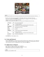
Page 57: ...ite mode is off see 4 2 1 Information Record Overwrite Setting will show And when the disk becomes full the icon will be changed to Click Emergency recording button icon will show Click Audio button i...

Page 58: ...hannel into Full Screen Activate mouse menu with right click at live mode and click ZOOM Drag a portion to zoom by mouse Double click mouse to exit zoomed screen This function works only in the full s...

Page 59: ...Z camera OSD setup screen and set up Tour and Pattern items Since these functions make use of a memory function of the camera itself user should set them in Camera OSD Once user completes the setup cl...

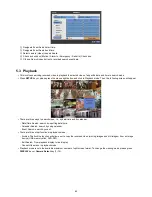
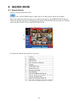
Page 60: ...Search This involves searching recorded video to playback the wanted video of a specific date and time Press SEARCH key on the viewing screen or Click Search menu at Function Keys and the following S...

Page 61: ...how pop up window on the screen If there is a recorded data The screen will show selected date time Click button for selecting cameras Selected camera will show the time bar 0 60 and It will be marked...

Page 62: ...owing screen will appear There are three ways to search video i e by date time and by calendar Date Time Search search by inputting date time Calendar Search search by using calendar Event Search sear...

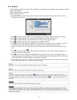
Page 63: ...Playback mode 1X PLAY PAUSE II PAUSE FORWARD I Frame by frame forward still image playback FF Fast forward playback changes to x2 x4 x8 x16 x32 x64 and Extreme with each press Go to End I Go to end o...

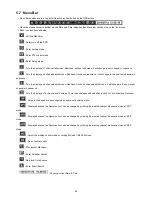
Page 64: ...apacity will show only for EXE Archive Click Start button Then Progress bar will appear and the storage process proceeds The progress bar does not show actual progress time Depending on to the file si...

Page 65: ...plit screen Additional click on 8 channels split screen it will change to the next eight channels in sequence Turn the display as 16 channels split screen There is no changes when additional click on...

Page 66: ...i e 0 255 Click direction buttons on the right hand side of HSTART VSTART to set adjust display poison If user wants every camera to have the same mode please click Copy to All Camera Choose OK to co...

Page 67: ...67 Intuitive CMS CMS Central Monitoring Station User s Manual This document contains preliminary information and is subject to change without notice...

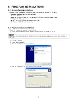
Page 68: ...itor SVGA or XGA 1024 x 768 Resolution 32 bit Color OS Windows 2000 SP4 or Windows XP only 6 2 Program Installation Method Please follow the program installation procedures below If an old version of...

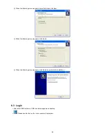
Page 69: ...ck Next When the following screen appears click Install When the following screen appears click Finish to complete the installation 6 3 Login After install CMS software CMS icon below appears on deskt...

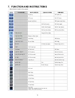
Page 70: ...MS Setting REMOTE SETTING Remote Setting DVR Setting ARCHIVE Archive Moving Image Playback Image Archive E MAP View E map image DVR Name DVR Activation DVR Select REMOTE CONNECT DVR Connection Network...

Page 71: ...ork setup 8 2 1 System Setup This menu is for CMS PC setup CMS VERSION displays current version of CMS Time Format displays current time and allow user to set date and time Display Option Default Divi...

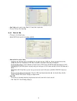
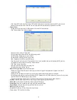
Page 72: ...sh IP Address Domain Name input IP address or Domain Name of DVR check with SETUP DEVICES Network in DVR Command Port input Administrator s number among port numbers set in DVR check with SETUP DEVICE...

Page 73: ...ing OK Exit without saving by clicking Cancel Remote Site Login Setup Input ID and Password Please do not input ID and Password if wish a popup window for logon ID and password to appear at the time o...

Page 74: ...n for CMS and enter without Password NOTE Before network connection be sure that HDD is installed Otherwise the DVR will not be connected over network If video does not display please check Local Sett...

Page 75: ...in Full Screen NOTE A selected channel is outlined in red Quad Screen Mode Click on QUAD SPLIT button and a quad screen will display The quad screen is in combination of 1 4 5 8 9 12 and 13 16 If use...

Page 76: ...ouse to back to the previous watch mode 8 3 3 Multi Screen CMS supports multi remote site connections simultaneously Server Drag Drop Drag Drop Remote Site of site tree to any screen Then all cameras...

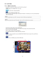
Page 77: ...operating Alarm Out of a selected DVR from a remote distance Click a channel number and Alarm Out of the corresponding channel will operate If user sees an intruder use this function to turn on a sire...

Page 78: ...ns Preset Control button Click on Preset Control button and the following screen will appear Please input Title and Preset Number When user completes the inputting please choose OK to confirm Press LO...

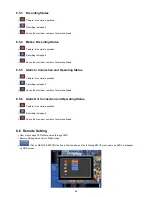
Page 79: ...ing status 3 HDD connection and its operating status 4 Recording status 5 Motion recording status 6 Alarm In connection and operating status 7 Alarm Out connection and operating status 8 Version 9 Rec...

Page 80: ...d Operating Status Camera is in normal operation Recording is stopped Above the maximum number of cameras allowed 8 5 6 Alarm Out Connection and Operating Status Camera is in normal operation Recordin...

Page 81: ...81 The setup procedure is same as that of DVR When the setup is completed do not click Exit button on the SETUP screen but click OK or Cancel button on the Remote Setup screen...

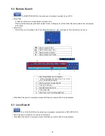
Page 82: ...y clicking LOCAL SEARCH button and the other is for searching event recorded data stored in DVR by clicking REMOTE EVENT button The list below describes functions of each part of the screen 1 Tool Bar...

Page 83: ...Search subsequent Year Search previous Month Search subsequent Month 1 Fast Forward Backward Playback Click to increase the speed by x1 x2 x4 x8 x16 x32 x64 and Extreme 2 Select Camera to be played ba...

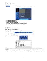
Page 84: ...Control Button Select time and click Fast Forward Backward button Click button to begin playback Use the control buttons below while playback Fast Backward Play Fast Forward Play Play Stop I Go to the...

Page 85: ...PEG file Click IMAGE SAVE button and the following screen will appear Input the name of the file to save and execute Save CAUTION If images are not saved properly click UNDO button and save again 9 5...

Page 86: ...86 Designate Archive start time Designate Archive end time Designate file name Select camera video to save Click on Start button to begin Archive...

Page 87: ...ayback mode PAUSE BACKWARD Frame by frame backward still image playback FORWARD Frame by frame forward still image playback REW Fast reverse playback FF I Fast forward playback DEINTERLACE Deinterlace...

Page 88: ...on the icon to exit program Please click on CMS PC setup and select remote site tab and the following screen will appear Please click on file open button and select the E Map file to load Please clic...

Page 89: ...on screen is as follows At Setup Record Setting by changing Settings you can estimate data size maximum recording days in advance Set DVR channel video type hard disk size of use After setting FPS per...

Page 90: ...Click EXE to AVI File and select a directory to save the converted AVI file Select a channel to convert Only one channel can be converted at once Select a Video Encoder between Microsoft and DIVX enc...

Page 91: ...91 CMS Web Client CMS Web Client User s Manual This document contains preliminary information and is subject to change without notice...

Page 92: ...ts automatic ActiveX installation Click the message above in the screen then following menu box will appear Click Install ActiveX Control and start installation Installation box will appears and click...

Page 93: ...d display Quit Finish program and close browser PTZ controller Must complete the control setting on its DVR and Cameras first Pan Tilt direction button Zoom In Zoom Out control button Focus Near Focus...

Page 94: ...up in Time bar Start Time Setting start time Camera Choosing camera number from 1 16 individually or all channels Play functions for playback Fast Backward Play Fast Forward Play Play Stop I Go to the...

Page 95: ...95 CMS Mobile Viewer CMS Mobile Viewer User s Manual This document contains preliminary information and is subject to change without notice...

Page 96: ...1 1 System Requirements There are no other requirements to run this program because it is specialized to perform on iPhone interface 12 1 2 Installation Turn on the iPhone then connect to App Store Mo...

Page 97: ...in by free When user clicks a button it will be turned to Click to start installation If user already has a iTunes account then input user s account to download the program If user does not have the a...

Page 98: ...m will be automatically installed 12 1 3 Site Registration Click icon on iPhone menu then below will show Move to and enter site information which are same as CMS site registration Enter Site Name IP...

Page 99: ...On window click one of the registered site and click To Select other channels click the channel bar below the Site Name If user wishes to change the channel among 9 16 then click 12 1 5 PTZ Control U...

Page 100: ...irection as user want Touch right side of the screen to move right and left side to move left Touch up side of the screen to move up and down side to move down In the same way touch any corners to cha...

Page 101: ...7 Uninstall Click the icon and hold for a while until the program icon shows x mark on the top left side Click the icon then it will ask to delete the program Click button to successfully uninstall th...

Page 102: ...nts This Program is designed and applied only for Android OS based Smart phones 12 2 2 Installation Turn on the phone then connect to Android Market Move to search menu and type mviewer then select pr...

Page 103: ...will be automatically installed in user s application menu 12 2 3 Site Registration Click icon on application menu then below will show Move to tab and enter site information which are same as CMS sit...

Page 104: ...of the registered site and click Move to tab and click icon To select other channels click the icon below the Site Name 12 2 5 PTZ Control Users are able to control PTZ with Android Phone Press volum...

Page 105: ...e left Touch up side of the screen to move up and down side to move down In the same way touch any corners to change the directions 12 2 6 Disconnection Users are able to control PTZ with Android Phon...

Page 106: ...lly uninstall the program 12 3 Blackberry Mobile 12 3 1 System Requirements This Program is designed and applied only for RIM Blackberry OS based Smart Phones 12 3 2 Installation Turn on the phone and...

Page 107: ...click icon in the download folder or applications folder and the following screen will be shown Click menu New to type the same site information with CMS site registration Enter Site Name and IP Domai...

Page 108: ...control PTZ by blackberry phone Press volume up button on the right side of the phone to zoom in Press volume down button on the right side of the phone to zoom out Press 1 9 number buttons to change...

Page 109: ...er version Memory 512Kb or Higher Device Smartphone Network Available all wireless networking method I e Wi fi HSDPA Wibro 12 4 2 Installation Prepare ActiveSync program to user s PC Available downloa...

Page 110: ...ng the license agreement then click Finish button Installation box will appear Click OK to start installation When installation completed following pop up will appear Click OK If following message app...

Page 111: ...111 NOTE Depending on mobile device successful installation message may not appear Click OK when license agreement message appear Move to Programs page to check whether CMS has installed...

Page 112: ...registered ID of the site Password Input the password of the registered ID Command Port Insert Command Port of the site Stream Port Insert Stream Port of the site Click Save then following screen wil...

Page 113: ...nnection Select a site then click Connect Live display screen of the site will appear if it is successfully connected Users are able to select a camera by clicking camera button Click Disconnect then...

Page 114: ...Program Menu System then click Remove Programs The currently installed list will show up Choose Mobile CMS on the list and click Remove Confirmation message will pop up Click Yes to complete uninstall...

Page 115: ...115 Keyboard Controller Keyboard Controller CP1200A User s Manual This document contains preliminary information and is subject to change without notice...

Page 116: ...485 13 1 1 Configuration Diagram I Single system configuration 1 Camera 1 DVR 13 1 2 Configuration Diagram II Multiple system configuration Multi Cameras 1 DVR Tx Tx Rx Rx DVR 1 RS485 RS485 Tx1 Tx1 T...

Page 117: ...n System ID and define the ID of DVR When user connects more than two DVRs then each DVR has to have a different ID Then move to Setup Device Camera PTZ Keyboard and select CP1200A Then choose PTZ pro...

Page 118: ...of each button The functions are same as Front buttons of DVR as follows DISPLAY change channel split screens in sequence of 1 4 9 16 1 SEQ turn on off Sequence function SPOT change the channel of a s...

Page 119: ...Z mode Press number keys ENT Hold for a while until double beep sounds key to change to Camera ID that wish to control If there is a corresponding Camera ID a full camera image will show up and PTZ co...

Page 120: ...120 Serial In POS ATM Serial In POS ATM User s Manual This document contains preliminary information and is subject to change without notice...

Page 121: ...to the DVR recognizes the USB converter When use a multi converter the port recognizes as Number 1 as its shortest line of converter consequently When use both single and multi converters single conve...

Page 122: ...t to USB port at front rear of DVR by using a converter 14 4 Link 14 4 1 Link Setup Click Setup Link then shows as below NOTE The above menu is only available on the DVR model with Serial In function...

Page 123: ...work Notification menu Set other POS ATM port as above Click OK to save the configuration 14 4 2 Schedule Setup Click Record Schedule then shows as below Tick the box item Alarm In Click the Time Date...

Page 124: ...rate 2400 bps Data Bit 5 bit Stop Bit 1 bit Parity None When the setup is done press enter to save the setting 14 5 3 OSD Display OSD items are to decide whether to display the information from the se...

Page 125: ...to input and analyze the serial data by clicking Pattern after tick the Auto box off Each item explains below Start Pattern Indicates the beginning of the new data when new designated data are receive...

Page 126: ...iter Decide the number of minimum characters in MCPL item to hide data under the designated number of characters Input the pattern of dummy data to Discard Pattern Choose the data which willing to dis...

Page 127: ...data 14 6 Search Using event search function Please click the Search Event Search menu on the pop up menu of the wallpaper then user will see the following screen It is possible to search the recorde...

Reviews: