Page
13
of
40
Issue: 6: 08/11/2018
DRAFT
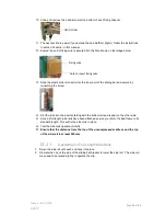
Figure 4: Foot section attachment
to bed end
Whether choosing the lower or high brackets ensure the bed platform is clipped into the same
level of bracket on all four legs.
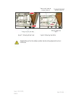
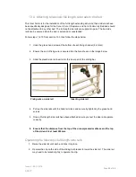
10. Slide the sliders into the end of the head platform section
(figure 7)
and secure with a
hand screw, repeat on other side.
11. Carefully align the two sections of the bed and slide together
(figure 8).
Tighten the turn
screw to secure then carefully place the bed onto its side to connect the controller.
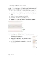
Figure 7: Foot section attachment to Figure 8: Connecting platform Figure 9: Test each function
bed end sections on the handset
Connecting the controller:
-
Connect cable 2 from the control box to the footend actuator
-
Connect cable 2 from the control box to the headend actuator
-
Connect cable 1 to the backrest actuator
-
Plug the mains plug into the wall socket and make sure all of the cables are secured
in the cable retaining clips.
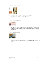
12. The transport brackets can be safely stored under the bed frame to prevent loss of the
brackets. This can either be done whilst the bed is on its side or by raising the bed to its
full height and attaching them underneath. The transport brackets can then be attached
to the fixing points onto the underside of the bed as indicated (figure 10). Ensure each
bracket is locked in place by securing with a turn screw.
13. Careful place the bed back onto its wheels and unpack handset and test functions (figure
9), by default the Trendelenburg function is locked out.
Figure 5: Collar locked Figure 6: Head section actuator
Press each
button (on
both sides)


