9
i
nstallation
Always disconnect power to the unit, before performing any service or maintenance.
Lamp and quartz sleeve are easily damaged. Exercise care when removing or replacing.
NOTE: Screws are needed to secure water purifier to mounting surface and ARE NOT included. Please use screws
appropriate for the mounting surface.
•
Unpack the water disinfection chamber and components following the steps in the “
Unpacking
” section on Page 5.
•
Be sure that you have read and followed all the instructions mentioned in the “Location” section on Page 5.
•
To allow for adequate room for installation and maintenance of the
Ultimate
TM
Ultraviolet Water Purifier refer to
“
Dimensional Data
”
Figure 1
and
Table 2
on Page 6.
•
Use the “
Dimensional Data
”
Figure 1
on Page 6, to mark the location of the bracket mounting pattern on the surface where
the unit will be mounted. (Refer to Dimensions “D”, “E”, & “F”.)
For added protection, a suitable drain pan must be installed under the purifier. The drain pan must be
plumbed to an adequate, free flowing drain to prevent water damage in the event of a leak. There are numerous leak
detection/flood stop devices, available on the market today, designed to stop the flow of water, reducing the chance of
water damage due to leakage. For more details regarding leak prevention and/or limiting damages due to leaks, please
contact the factory.
Installation Steps 1 to 10
1. Install the bottom bracket to the mounting surface (with screws not included). The lip of the bracket should face down.
2. Place top bracket over the static gland nipple where the lip of the bracket faces up (refer to “
Dimensional Data
”
Figure 1
on Page 6 ). Install bracket nut onto the static gland nipple so that it holds the bracket against the top of the chamber - hand
tighten only. Place the chamber & top bracket assembly onto the bottom bracket. (Upward facing fingers on the lower bracket
straddle the bottom rim of the chamber.) Align the top bracket so that it faces the mounting surface and is in line with the
bottom bracket. Secure the top bracket to the mounting surface (with screws not included).
3. Slowly slide the quartz sleeve into the disinfection chamber, guiding it through the gland fitting until it seats into bottom
center of water purifier.
NOTE
: Use care to keep the quartz sleeve parallel to the chamber. Angling the quartz sleeve in any
direction could result in the breakage of the quartz sleeve.
4. Place the O-Ring over the end of the quartz sleeve and push the O-Ring down the quartz sleeve until it is seated against the
static gland nipple.
5. Place the Teflon
®
washer over the quartz sleeve until it rests on the O-Ring.
6. Install the static gland nut over the quartz sleeve and onto the static gland nipple. Be careful when installing static gland nut.
Firmly tighten the static gland nut by hand. Hand tightening will provide the required seal.
DO NOT USE HAND TOOLS
,
tightening with hand tools is likely to cause the quartz sleeve to break.
7. Insert the lamp part of the way into the disinfection chamber, then attach the lamp socket connector to the lamp; make sure
the connector is fully seated on the ultraviolet lamp. Carefully slide the lamp into the quartz sleeve.
8. Lower,
DO NOT DROP
, the ultraviolet lamp into the quartz sleeve so that the lamp is resting at the
bottom of the quartz sleeve.
9. Thread the translucent sight port plug (connected to the lamp socket connector) into the static gland nut and hand tighten.
10. Install Grounding Kit following the instructions in the “
Grounding Kit Installation
” on page 10.
•
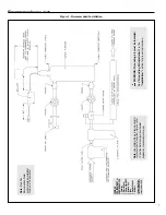
Plumb unit following the recommended installation in “
Unit Installation
”
Figure 2
on page 7.
•
When all plumbing connections are complete, allow water to enter the water purifier at a low flow rate, until the purifier is
full. With the purifier pressurized, it should be checked for leaks. If the unit leaks, make sure that the static gland nut is firmly
tightened.
DO NOT
use seal compounds to stop the leak. If the leak continues, close the inlet shut-off valve; release the
pressure on the unit and drain. Inspect the quartz sleeve for damage. Be sure that the O-Ring and Teflon
®
washer are on in the
correct order on the quartz sleeve (not inside the static gland nut).
•
Re-pressurize unit and check for leaks. Once it is determined that there are no leaks, the inlet valve can be full opened.
•
Once the plumbing hook ups are made, it is good practice to disinfect the “downstream” plumbing between the purfier and
point of use. This is done by introducing chlorine or other disinfectant solution directly into the purifier chamber, a 100 parts
per million of chlorine is suggested.
(Continued on Page 10)
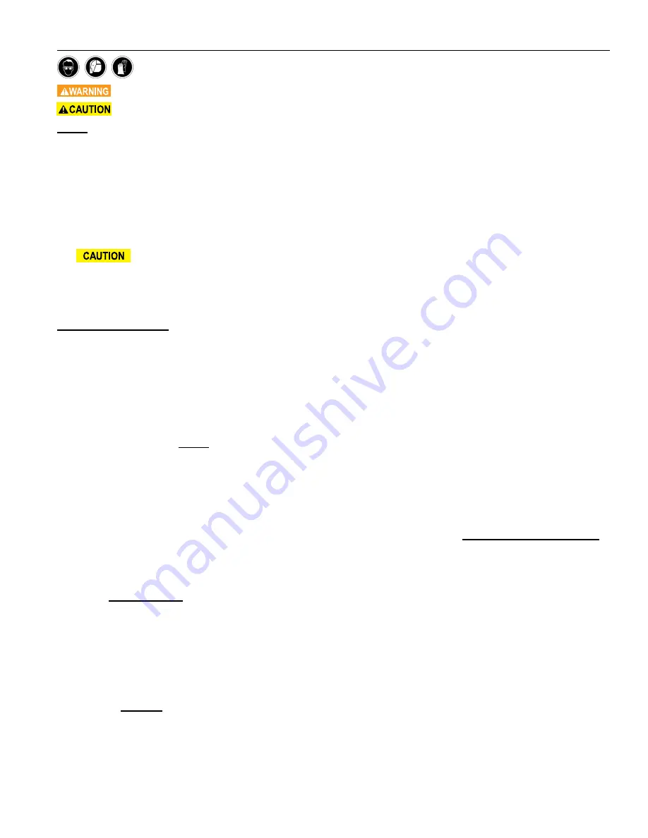
IN ORDER TO PERFORM THIS TASK, BE SURE TO WEAR THE FOLLOWING SAFETY
EQUIPMENT: SAFETY GOGGLES OR A FACE SHIELD, AS WELL AS GLOVES


