4.
Unclip
the
four
multi
‐
pin
wiring
quick
connects
from
the
110W
Blower
Drive
Board.
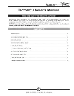
5.
Remove
the
four
(4)
screws
securing
the
Blower
Drive
Board.
6.
Remove
the
Blower
Drive
Board.
The
multi
‐
pin
wiring
quick
connects
are
located
on
the
right
of
the
board,
outlined
in
yellow
.
Page 3
7.
On
the
NEW
Board,
Check
that
Jumper
1
is
ON
and
Jumper
2
is
REMOVED
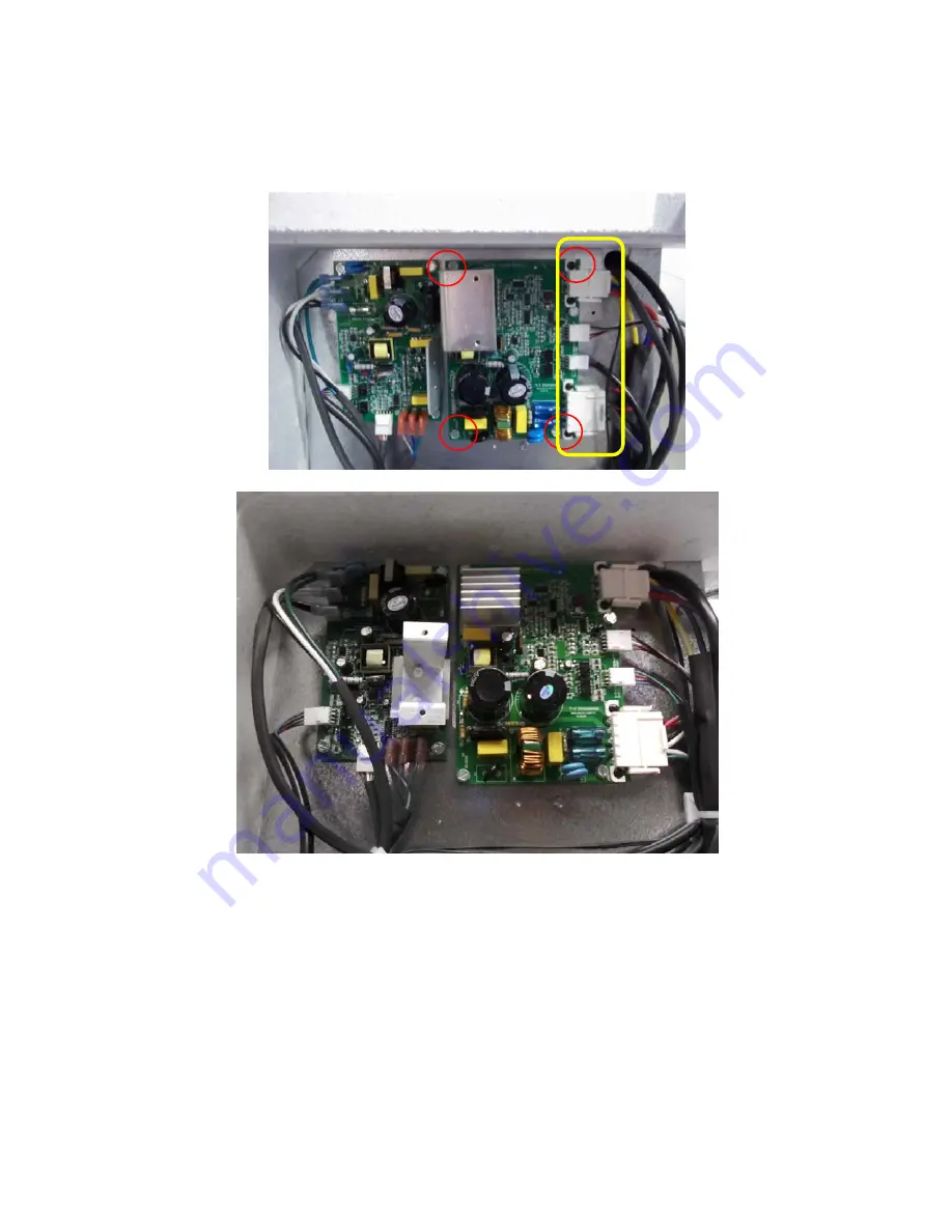
8.
Place
the
replacement
Blower
Drive
Board
in
the
same
position
and
orientation
as
the
one
removed.
Replace
the
four
(4)
screws.
Reconnect
the
wiring
connectors
in
their
original
positions.
9.
Replace
the
white
polystyrene
insulation
and
the
exterior
metal
side
with
the
original
four
screws.
Repeat
this
procedure
if
both
Blower
Drive
Boards
require
replacement.
Once
installation
of
new
components
is
complete,
reinstall
the
fiter
top
and
four
thumb
screws.
The
ducting
may
then
be
re
‐
attached,
and
the
RecoupAerator
plugged
in
and
turned
on.
Effective
07/2011
–
current
Serial
Number
13685
and
on
Revised:
Wednesday
September
18
th
2013