Ultimatte-9 Operations Manual
March 1, 2000
7
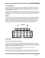
7. Status Display LEDs
There are 7 green LEDs and one red LED that provide status information.
•
=
On power up all LEDs blink on and then off followed by being turned on one at a time starting
with G1 and shifted left through G7 and R
•
=
On the successful completion of internal diagnostics the following information is displayed on
the LEDs as shown in the table below where:
•
=
‘1’ indicates the led ON condition.
•
=
‘0’ indicates the led OFF condition.
•
=
‘T’ indicates the led is toggling.
R
G7 G6 G5 G4 G3 G2 G1
COMMENTS
1 0 0 0 0 0 0 1 Boot
Mode
T
0
0
0
0
0
0
1
Blinks when Unit ID select does not match ID (1-4)
0 0 0 0 0 0 1 0 Programming
Flash
0 0 0 0 0 0 1 1 Programming
LCA
0
/1**
0 0 0 0 1 0 1 Loading
LCA
number
1
:
IOFT
0
/1**
0 0 0 0 1 1 0 Loading
LCA
number
2
:
UIC
0
/1**
0 0 0 0 1 1 1 Loading
LCA
number
3
:
COLORIZER
0
/1**
0 0 0 1 0 0 0 Loading
LCA
number
4
:
AMBIANCE
0
/1**
0 0 0 1 0 0 1 Loading
LCA
number
5
:
DEFOCUS
0
/1**
0 0 0 1 0 1 0 Loading
LCA
number
6
:
ADVANTEDGE
0
0
1
0
0
0
0
0
Processing a command as a result of a serial transfer
from the Smart Remote
0
0
0
1
0
0
0
0
Processing a command as a result of a serial transfer
from the Editor port
0
T
0
0
0
0
0
0
Blinks every 4 seconds = Reference Video present
Blinks every 6 seconds = No Reference video present
Table 2: LED Status
**
An "ON" condition indicates a failure in loading the LCA.
8. Fuse Replacement
Two (2) 5mm X 20mm fuses must be installed on both the Main Unit and Smart Remote. Fuses
are positioned as shown below.
opposite side.
Second fuse on
FUSE POSITIONING
REMOTE
MAIN UNIT

