9
8) ROPE MOUNTS
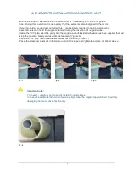
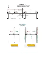
Fig.7
Fig.8
A MastrAnt P kit of ropes of suitable length is provided for the construction of the tie rods.
Tie the rope to the right and left C supports through the double junction eyelet (Figure 7)
Then simply attach the rope (one section) to the aluminium stick placed on the motor unit (fig.8). Cut
of the excess rope from one of the two C supports only when the correct length has been obtained.
The
elements must not
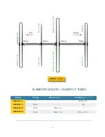
look up, the correct tension of the strings is given by the alignment of the C
supports (fig.9) which must not be higher than the motor drive tube
A possible downward trend is recommended
, ideal to align the loops with the same inclination of
normal elements (no loops) of your antenna (Figure 10)
Three holes in the stick will allow you a small final correction to the tension of the strings without
removing the rope from the junction.
Fig.10
C
Fig.9
C
C
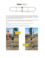
Natural inclination telescopic
element
Ideal inclination loop
element

