7
5) LOWER ELEMENTS ASSEMBLY
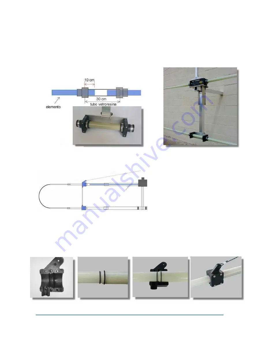
Install the lower elements on the lower support just like on a motor unit.
In Fig.1 the scheme of the position and placement of the elements into fiberglass tube
mounted on the support is displayed.
Insert the element 10 cm and lock it with the outer bands of rubber sleeves.
6) SUPPORT ROPES INSTALLATION
The strings are attached to the elements by means of two special ABS collars (fig.2) placed in the central
junction of the telescopic element, to this junction the thermos-shrinking tubing does not apply.
Place two o ring elemens as shown in fig.3-4
Close the two ABS shells by means of M4 screws (Figure 5). Eeven closed, the ABS holder will rotate on
itself, this is normal, the internal notch placed between the two o rings will prevent it from slipping inward.
Fig.2
Fig.3
Fig.4
Fig.5
support C
Fig.
A
B


