


IV.
MOVING OVER FLAT SURFACES
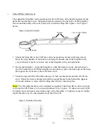
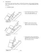
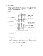
Start with the load inclined in the balance position as shown in Figure 7.
Grasp the extension handle with your left hand and the main handle with
your right and proceed as follows:
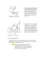
1. Tilt the load back by pulling down on the extension handle.
You will feel some of the weight of the load.
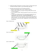
2. PULL or PUSH the control switch to move the load up or
down along the frame. Find the point where the load is
well balanced over the wheels. When the balance point
is found, very little effort is required to hold the load
steady, and the operator can concentrate on pushing the
load to the final destination.
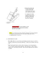
3. At the final destination Ultra Lift takes the work out of
setting a heavy load down and also protects the load from
damage during the process. The problem with a standard
hand truck is that the operator often reaches a point where
“the load takes over” as it is tilted down and slams to the
ground. Such impact can cause costly damage to delicate
items such as computers, copy machines, and appliances.
Ultra Lift power eliminates the problem. To set the load
down, PUSH the control switch and “power” the load to
the ground. With the edge of the load on the ground,
tilt the load forward until the bottom of the load is flat
on the ground. For very heavy loads, drop the leverage
bar before tilting the load forward and use foot pressure
for added control.
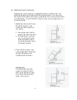
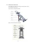
A. FOUR WHEEL DOLLY
If the load must be moved a long distance over a flat surface,
assemble the four wheel dolly before breaking back the load.
Refer to Section VIIIA for assembly instructions.
Break the load back until the dolly wheels are on the ground.
PUSH or PULL the control switch as required to stabilize the load
on the four-wheel dolly and push it to the final destination. Set
the load down as described above and disassemble the dolly.
-6-
Summary of Contents for 1500
Page 28: ... ii ...


